Hello,
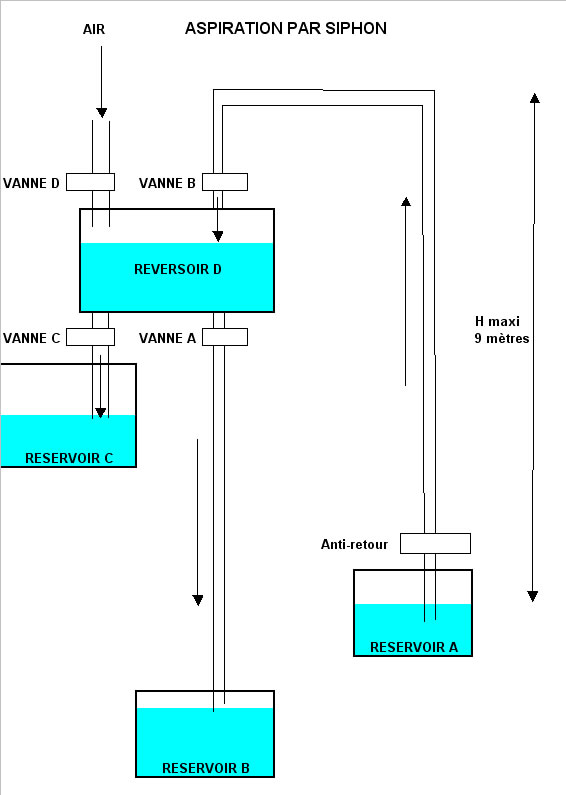
Below a sketch of a siphon lifter that could work simply, just solve the way
two valves must be closed or "replaced":
- valves A and B are open, closed C and D
The water flows by siphon from tank A to B
- in passing the tank D is filled
we close valves A and B then we open C and D
- water flows from tank D to tank C
then when the tank D is empty
- we start a cycle again
the maximum pumping height is 9 meters
the capacity of the tank D is limited by the volume of the
"siphoning" line
What are your ideas, opinions, observations to replace the valves?