Generator problem Aster generator Sobemo 20 kW

And if they were repairing rather than throwing and change? Rediscover the pleasure of the repairs yourself. How to diagnose a problem or find spare parts? Repair itself is way to save money generally!
paul2010
I learn econologic
I learn econologic
posts: 13
Registration: 15/03/10, 18:05

Generator problem Aster generator Sobemo 20 kW


by paul2010 » 15/03/10, 18:29

Hello,

First of all I wanted to thank this forum which is very useful for the info that we can find there it served me more than once.
Usually I manage on my own but here I would need a little help.
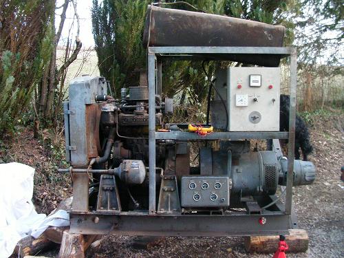
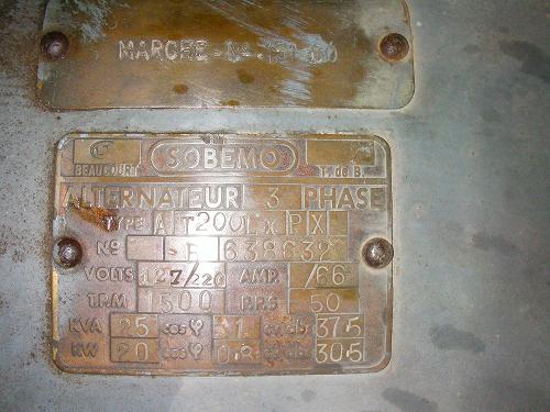
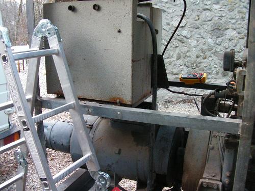
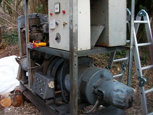
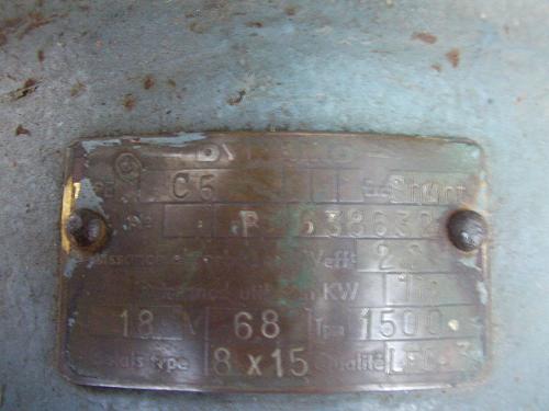
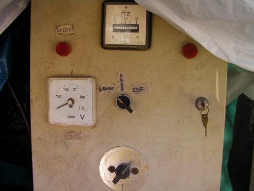
So I got a 20KW aster generator generator sobemo but everything is not connected in fact it served as a backup group for a box, so it worked.Perso I would just use it as a group alone without connecting it to the house. For the moment when I put a voltmeter at the terminals of the tranfo I only have 17v. I specify that it is possible to adjust the voltage and the frequency via the control panel but that the ((voltage regulator (button at the bottom of the electrical cabinet on photo 1)) it is not connected to anything. And I wonder what the connected to be able to increase or lower the voltage. I am attaching some photos ca m will help you explain. For the moment the connection is as follows:
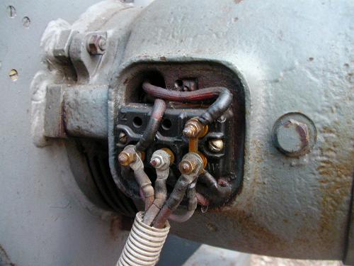
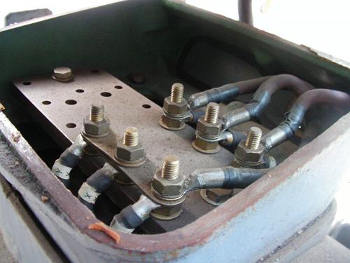
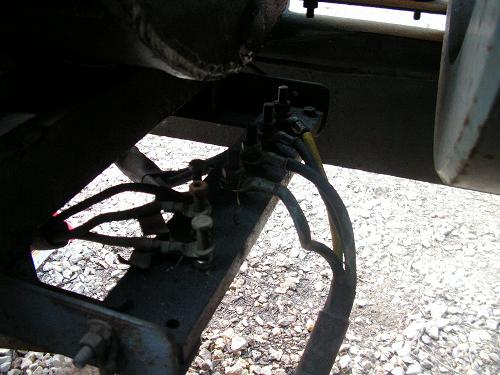
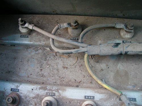
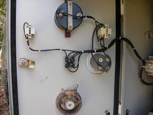
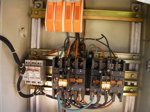
the wires that we see on photo 3 coming out of the generator head (which must be the exciter) are connected to a plate on photo 5. On this same plate come three cables which come from the photo 4 (which is the photo taken on the top of the generator). These same wires those of photos 4 which go on the stage (photo5) leave towards a tranfo (that we saw from above photo 6 and from behind photo 7 ) where they are connected to 220 terminals. Besides, we see that there are 380 terminals. Here I hope to be quite explicit because I am not a pro. So my questions are:

To which element should I connect the voltage regulator (button at the bottom of the electrical cabinet in photo 1)?
Is it normal that I only have 17V across the transformer (photo 6 and 7)?
Are the wires coming from the exciter (photo3) ok on the plate (photo5)?
What is the purpose of this transformer (which is 31,5 kva)? on small groups I don't see a tranfo hence my question

Here I thank in advance those who will have the patience to answer me.

cordially
paul
Image
Image
Image
Image
Image
Image
Image
Image
Image
Image
Image
Image
0 x
User avatar
zorglub
I posted 500 messages!
posts: 501
Registration: 24/11/09, 10:12

hotel


by zorglub » 15/03/10, 19:44

Good evening

check that the connections coming out of the exiter are well connected to the alternator
logically the regulation must play on the exciter's excitation
these cables may have been disconnected during decommissioning if this is the case by rotating the system you will have a low voltage due to the remanence (which seems to be happening)
remains to know the principle of the excitation of the exitor
is it direct current? (which would be logical)
see if you have two cables coming from this exciter
it will certainly be those which were used for the regulation (in the cupboard)
look on the exciter plate if the current is continuous in the photo, we can not read correctly - it seems to me to read 18 ampere 6.8 volts and dynamo (it will therefore be continuous
note that it takes a lot of amperes and little tension
on this regulation you can either try or
to put the 2 wires in contact with the rotation you will have a maximum voltage and current which will excite the inductors of your exciter
either put a resistance of a few ohms and supporting a dozen amperes to close this circuit
alternator voltage will go up

if this group started on "lack of voltage" the starting was done at the same time as the voltage regulation but you will have to inquire to be on
meanwhile if you need further advice i will gladly help you

nb: we have several kinds of alternator
in principle the alternator is excited by current produced by the exciter in direct current
for others, we have rectifiers that produce the cc from
inducers

ps certain photos, I could not load them
0 x
every morning you look naked in a large ice after 3 minutes you will see that your home and your worst picture ......
Christophe
Moderator
Moderator
posts: 79374
Registration: 10/02/03, 14:06
Location: Greenhouse planet
x 11064


by Christophe » 15/03/10, 19:47

0 x
User avatar
zorglub
I posted 500 messages!
posts: 501
Registration: 24/11/09, 10:12


by zorglub » 15/03/10, 19:56

your transformer is a 220/380 transformer which was used to change the voltage
currently it is powered by the generator

other detail can we have a photo to read what is written on the lower cabinet (the small one)
on that you should have parameters that are clearly related to the exciter - on the photo, we don't read well
or tell me what the measuring devices and control buttons give
0 x
every morning you look naked in a large ice after 3 minutes you will see that your home and your worst picture ......
User avatar
Forhorse
Econologue expert
Econologue expert
posts: 2491
Registration: 27/10/09, 08:19
Location: Perche Ornais
x 364


by Forhorse » 15/03/10, 20:09

Off topic ... but we quickly recognize the people who had internet after the golden age of 56k :|
0 x
User avatar
zorglub
I posted 500 messages!
posts: 501
Registration: 24/11/09, 10:12


by zorglub » 15/03/10, 20:12

I seem to read on the plate of the "schunt" exciter which would mean that on these 2 wires you would need a rehostat (variable and adjustable resistance) supporting the maximum current of the excitation of the exciter)
0 x
every morning you look naked in a large ice after 3 minutes you will see that your home and your worst picture ......
User avatar
zorglub
I posted 500 messages!
posts: 501
Registration: 24/11/09, 10:12


by zorglub » 15/03/10, 20:15

. but we quickly recognize the people who had internet after the golden age of 56k


I got it before! at the connection, and it was expensive,
but worse my first computer was a cassette which programs had to be made in 87
0 x
every morning you look naked in a large ice after 3 minutes you will see that your home and your worst picture ......
paul2010
I learn econologic
I learn econologic
posts: 13
Registration: 15/03/10, 18:05


by paul2010 » 15/03/10, 20:53

Hi,

Thank you for looking into my case.
DSL for photos
I give all the photos + 3 others from the wardrobe
I resized them
It is true that it is more readable and that it goes much faster to upload : Cheesy:

Image
Image
Image
Image
Image
Image
Image
Image
Image
Image
Image
Image

cordially
Paul
0 x
paul2010
I learn econologic
I learn econologic
posts: 13
Registration: 15/03/10, 18:05


by paul2010 » 15/03/10, 21:09

I forgot on the photo where we see marked dynamo (photo9) is written this:

type c5 Exct Shunt
No. B 638.632
Power absorbed in Cv Efft 2,2
Useful power in Kw 1,2
At 18 V 68 RPM 1500
Broom type 8x15 Quality LFC- 3

cordially
Paul
0 x
paul2010
I learn econologic
I learn econologic
posts: 13
Registration: 15/03/10, 18:05


by paul2010 » 15/03/10, 21:46

RE,

So thinking about it, the 3 fis coming out of the exciter (photo 3)
have nothing to do on the board with the 3 cables coming out of the generator (photo 5) (they must have been put there for transport)

Am I wrong?

Thank you
cordially
Paul
0 x


  • Similar topics
    Replies
    views
    Last message

Back to "failure, troubleshooting and repair: repair yourself? "

Who is online ?

Users browsing this forum : No registered users and 98 guests