Need help with wind turbine development

Renewable energies except solar electric or thermal (seeforums dedicated below): wind turbines, energy from the sea, hydraulic and hydroelectricity, biomass, biogas, deep geothermal energy ...
Alain G
Econologue expert
Econologue expert
posts: 3044
Registration: 03/10/08, 04:24
x 3


by Alain G » 12/09/09, 19:06

Hello André

It was only to increase the capacity in amperage that I proposed three bridges, finally to obtain better cooling.
He could very well use that of his already ready automobile alternator.
:D
0 x
darwenn
I posted 500 messages!
posts: 510
Registration: 16/07/09, 17:43
x 9


by darwenn » 12/09/09, 23:31

If I say no stupidity, the diode bridge that is sold with the optional generator also has 3 diode bridges. Finally it's a detail : Cheesy:
0 x
darwenn
I posted 500 messages!
posts: 510
Registration: 16/07/09, 17:43
x 9


by darwenn » 13/09/09, 20:36

A question in passing, is the direction of rotation important? I mean if I profile my blades to turn counterclockwise unlike my other blades which turned clockwise does it matter or not?
0 x
User avatar
loop
Grand Econologue
Grand Econologue
posts: 816
Registration: 03/10/07, 06:33
Location: Picardie


by loop » 13/09/09, 21:25

Good evening,

The direction of rotation of the rotor does not matter because the three-phase alternator you are using does not have a preferred direction of rotation.
On the other hand, the blades only have one direction of operation.

A+
0 x
darwenn
I posted 500 messages!
posts: 510
Registration: 16/07/09, 17:43
x 9


by darwenn » 13/09/09, 22:51

yes I am not talking about putting the blades in the other direction so that the propeller turns in the opposite direction : Cheesy: I was talking about creating the profile so that they turn the other way around.
0 x
Alain G
Econologue expert
Econologue expert
posts: 3044
Registration: 03/10/08, 04:24
x 3


by Alain G » 13/09/09, 22:55

Darwenn

Looping is right, it doesn't matter
since it is a three-phase gen.
:D
0 x
Stepping behind sometimes can strengthen friendship.
Criticism is good if added to some compliments.
Alain
jumpy
I discovered econologic
posts: 3
Registration: 16/09/09, 17:46
Location: 38 Isere


by jumpy » 16/09/09, 18:01

I was looking for something else and came across this post.
I can not help but give a paw of the paw!
It's normal that your blades are malfunctioning ...
Take the case of the ones you plan to make.
at 10 cms from the hub, for a propeller which turns at 200 rpm, the linear speed is:
3.14 x 10/1000 x 2 x 200/60 = about 0.2 m / s
at the end of the blade:
3.14 x 2.4 x 200/60 = 25 m / s

In these two places, you want to put the same angle of 4 °. At the tip of the blade, the contribution to the force will be maximum, at the root of the blade, the contribution to the force will be zero. The blade tip being the most fragile (because the thinnest and the farthest from the axis), it flutters. It must sound a bit if you listen carefully.

This is why the blades must be twisted. The pitch angle must be calculated for each distance from the hub so that the contribution to the force of the entire blade is the same regardless of the linear speed at this distance. In practice 10 equidistant points are sufficient.

It complicates the size of the blade a bit. Once you have your block of the desired shape in plan, you have to trace on the sides the position of the BA and BF so that you can cut the blade directly to the right twist.
0 x
darwenn
I posted 500 messages!
posts: 510
Registration: 16/07/09, 17:43
x 9


by darwenn » 17/09/09, 07:57

Basically the tip of the blade must be perfectly vertical like the plane of rotation, and the rest of the blade must be twisted, right?
0 x
jumpy
I discovered econologic
posts: 3
Registration: 16/09/09, 17:46
Location: 38 Isere


by jumpy » 17/09/09, 10:34

No, not vertical, but with a slight inclination.

Each point of the blade travels a "path" = 3.14 x diameter at each turn. The further away from the axis, the greater the distance traveled. OK?

Then, the tilt angle must be calculated so that each point of the blade "advances" the same horizontal distance for 1 turn. Obviously, the wind turbine blade is not a propeller blade and therefore does not advance, but the reasoning is the same. This is to balance the contribution to the force along the blade, to distribute the mechanical forces as well as possible and above all to ensure the aerodynamic efficiency of the blade. Still fine?

The farther away from the axis, the smaller the twist angle from the vertical plane must be.

Suppose we want a pitch of 500mm; that is to say that each point of the blade will have to advance by 500 mm with each revolution.
Suppose now that the blade is screwed perfectly in the air, it is a little daring, but it allows for roughing.

First point: 10 cm from the axis of rotation. Distance covered in 1 lap = 3.14x0.1 = 0.314 m.
The angle of inclination can be represented on a triangle whose opposite side is the value of the step and the adjacent side is the value of the distance traveled. We then have blade inclination = arctangent (P / D). In our case inclination = 57.9 °.
This angle is therefore the inclination that the blade must have relative to the vertical plane at 10 cm from the axis of rotation.

We start again: second point 20 cm from the axis. P = 0.5.
D = 3.14x0.2 = 0.628 I = arctan (0.5 / 6.28) = 38.5 °

And so on until the last point 120 cm from the axis.
D=3.14x1.2=3.77 I=arctan(0.5/3.77)= 7.6°

So much for the angles of inclination that the blade must have. We realize that it must be twisted ... Still with me?

To make the blade, you must first cut a thick rectangle in CTP, then cut out the projection shape of the blade (rectangular shape, more rounded shape, "lollipop", "spatula", etc ...) . I recommend the rectangular shape for the first blade.

For each point calculated previously (every 10 cms), we will measure the width of the blade, then calculate the difference in height between BA and BF that the angle of inclination imposes on us. We add to that the height necessary to cut the profile (Naca have a reference line passing through the BA while a Clark Y has a reference line which is its flat underside). And the BA + BF values ​​are transferred directly to the blank of the blade. It is then sufficient to cut the blade while respecting these points as the reference line of the profile. The twist and the profile are then cut directly from the mass. It's long, but very stable over time. There, it is more robust and difficult to visualize for who has never cut a blade ...
0 x
User avatar
loop
Grand Econologue
Grand Econologue
posts: 816
Registration: 03/10/07, 06:33
Location: Picardie


by loop » 17/09/09, 12:51

Bonjour,

A little complicated explanations.
:|
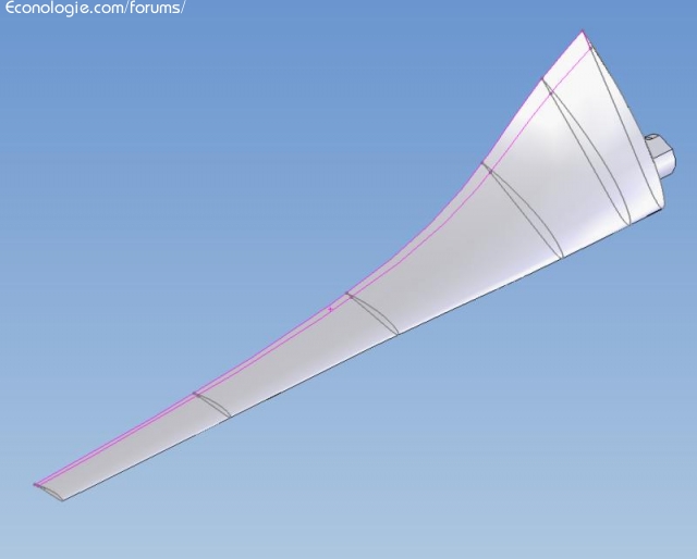
The twist is necessary when one wishes to make all the sections of the blade work at the same optimum angle of incidence, ie 6 °.
In a previous message I had drawn the method for graphically determining the blade tip pitch according to the chosen TSR. For the other parts of the blade, the TSR decreases as one approaches the axis of rotation.
We can see that for a tsr of 6, the outer half of the blade hardly needs twisting (it is this part which provides the bulk of the power).

Here is a picture of what it looks like in 3D

Image

Theoretically, the final profile at the root of the blade is set at 6 ° from the axis of rotation.
In practice, the blade root is used for its fixation and this part has almost zero efficiency.

A+
0 x


  • Similar topics
    Replies
    views
    Last message

Back to "hydraulic, wind, geothermal, marine energy, biogas ..."

Who is online ?

Users browsing this forum : No registered users and 197 guests