Gillier-Pantone on a Transporter T3

Edits and changes to engines, experiences, findings and ideas.
User avatar
manoria68
Éconologue good!
Éconologue good!
posts: 301
Registration: 07/10/08, 12:34
Location: ATLANTIS
x 2


by manoria68 » 14/10/08, 22:39

Hello,
I will follow your advice (after study and some time to settle ideas)

Anyway, you have to do something because where I connected the outlet of my reactor, its does not suck unless I block the air inlet. attached diagram
At this time the sa running (in multi fuel) with therefore my engine injection deactivated and secondary injection ramp activated.

Image

Because when I accelerate, I need air, and if it is obstructed where it is indicated, the engine cannot take turns.
The reactor cannot pass as much air
of course, its would cool it too much

So make a venturi ...

I think of sanitary PVC, 2 identical reductions together, I would go to a DIY store. If I don't find my happiness, I would make one myself.
On the other hand, if someone could give me the final ratings to size it up

I will try this WE, but on the other hand I do not think that it will work for multi fuel, it is still necessary that its sucks a lot, I think that it will work very well for doping

but hey, as there is no equivalent to my editing, I take the test, at worst I would waste precious time lost in front of the TV :)
0 x
jcf
I learn econologic
I learn econologic
posts: 40
Registration: 21/11/04, 22:58


by jcf » 16/10/08, 11:54

manoria68 wrote:Okay, so in order my editing:

For the signal recovery, it is copied identically to that of the original injection. (used function of the card)

Image

Where does this card come from? Are you the one who made it or is it a salvage or a purchase specially for that?

I also have the possibility to send a PWM signal, so to send a sygnal in injectors cyclic variable variable (not used) in french: open injectors 0 100% but this function is not used.

I don't quite understand what it means. You mean that you can minimize the increase in the duration of the original signal in the replicated signal that you send in your secondary ramp?

The signal thus feeds a secondary injection ramp placed in the passenger compartment.

Image

This feeds the reactor.

It is powered by a tank mounted separately from the car

[...]


Tell me if I'm wrong, but I have the impression that in your assembly, there is no injection of water into the engine?
A+
JC
0 x
User avatar
manoria68
Éconologue good!
Éconologue good!
posts: 301
Registration: 07/10/08, 12:34
Location: ATLANTIS
x 2


by manoria68 » 16/10/08, 12:31

The signal cannot be changed with my montage.
But I don't think it would help, the lambda probe will readjust the signal.
In addition, I start with the original injection,
The card is from my conception of another diverted realization.
if you want to do the same thing, take the NLC card instead by shunting the microcontroller, or by putting a switch that switches the signal from the injection of the engine to the secondary ramp.

For water injection, it is mixed with the fuel injected by the secondary rail

voilou!
0 x
Manoria 68, fried researcher, technician of its oil mill
jcf
I learn econologic
I learn econologic
posts: 40
Registration: 21/11/04, 22:58


by jcf » 16/10/08, 14:10

manoria68 wrote:The signal cannot be changed with my montage.
But I don't think it would help, the lambda probe will readjust the signal.

Ok, with me it would not work because no lambda!

manoria68 wrote:For water injection, it is mixed with the fuel injected by the secondary rail
voilou!

Okay ! And you manage to have a homogeneous mixture? I would really like to make two signal replication cards, one for fuel and one for water, and that each of the two is sent to the secondary rail by dedicated injectors.
But I don't know what to use as injectors that won't stick to water!
However, this type of assembly would be the only one making it possible to determine exactly the optimal water / fuel ratio in the reactor compared to the calculations made by the original injection of the engine.

A+
JC
0 x
User avatar
manoria68
Éconologue good!
Éconologue good!
posts: 301
Registration: 07/10/08, 12:34
Location: ATLANTIS
x 2


by manoria68 » 16/10/08, 14:53

Yes, for sure, having separate injectors would be ideal.
0 x
Manoria 68, fried researcher, technician of its oil mill
jcf
I learn econologic
I learn econologic
posts: 40
Registration: 21/11/04, 22:58


by jcf » 16/10/08, 15:10

manoria68 wrote:Hello,

Image

So make a venturi ...

I think of sanitary PVC, 2 identical reductions together, I would go to a DIY store. If I don't find my happiness, I would make one myself.

Not sure if you need to worry about PVC, I think you can make it a lot easier.

However to advise you, I need to understand, because on your editing I have a doubt:
Image
At the red bar that I drew is your flow meter or your throttle?
In both cases, where is the other (the butterfly or the flow meter)?
A+
JC [/ img]
0 x
User avatar
manoria68
Éconologue good!
Éconologue good!
posts: 301
Registration: 07/10/08, 12:34
Location: ATLANTIS
x 2


by manoria68 » 16/10/08, 15:27

Hi, thank you for devoting yourself to this before I do something unnecessary

Where is the red line, it is the gas butterfly.
I don't have a flow meter

It is between the latter and the air filter that I think to put the venturi
0 x
Manoria 68, fried researcher, technician of its oil mill
jcf
I learn econologic
I learn econologic
posts: 40
Registration: 21/11/04, 22:58


by jcf » 16/10/08, 21:58

manoria68 wrote:Hi, thank you for devoting yourself to this before I do something unnecessary

You're welcome, I'm unfortunately not here this week so I hope I can get you ideas by then!
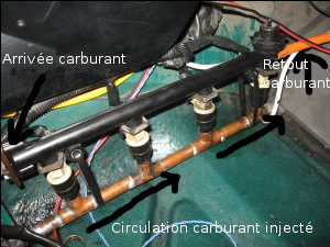
manoria68 wrote:Where is the red line, it is the gas butterfly.

Okay, so this cable is connected to the cable that goes to the accelerator in the passenger compartment.

manoria68 wrote:I don't have a flow meter

Really?
How does the calculator calculate the injection? Simply by the position of the butterfly? (you see electrical connections on this butterfly?)
Are you sure there is not a valve that measures the air flow in your air filter (no electric wire connected to it)?
Or is there a capsule which measures the vacuum between the intake manifold and the outside and which deduces the amount of air which must be being swallowed by the engine according to its speed?


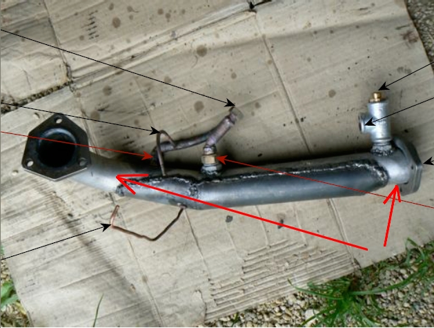
The U-shaped pipe to which you connected the outlet of your pantone, what was it used for? Ah yes, on your diagram you indicate that there was the idle solenoid valve, right?


The shutter that you drew on your diagram is it you who added it so that it sucks enough on the pantone, right?


manoria68 wrote:It is between the latter and the air filter that I think to put the venturi


It would surprise me that it spoils ...
The best is to place a tube whose end is biased just after your butterfly.
I think the problem in your current assembly is that the U-tube on which you plugged the output of your PMC short circuits your PMC too much since the air has easier to pass through this U than to pass through the PMC then by the end of the U.
In addition, if the assembly corresponds well to your diagram, the idle adjustment valve is located after your PMC. However as soon as your engine takes turns, I think that this valve closes since its only role is to regulate the idling. Suddenly, no more suction at all on your PMC.

If I was not mistaken in what I tell you above, here is how I would do it for you (non-destructive mounting for your air box):
1- the end of the U-tube which is connected just after the butterfly valve, you connect it with the idle control valve directly on the breather (it is the other tube which goes from the cylinder head cover to the air box).
This way it will less disturb the venturi effect when arriving in the middle of the air box.

2- by the connection thus released just behind the throttle valve, you slide a tube which fits directly there and you push it in until its end reaches the middle of the circle formed by the section of the throttle valve. Give at its end the bizarre shape necessary for the venturi effect. Check before making all this modification (including my number 1), that the tube thus pushed does not bang against the throttle when it is in full opening (yes, it would be annoying).

Image
I hope that my explanation and my diagram are roughly understandable (not easy to do from a distance!).


Normally, the section at the throttle level is narrower than the air box behind it, so you can get a venturi effect easily without having to do a whole assembly with discounts etc. This is what I did and at home depression is top on all diets.

Your ethanol injector I imagine that you can leave it on the outlet line from PMC to air box, it will also benefit from better suction.

By the way, at the air intake of your PMC, you put a filter? Because it is still better for your engine, even if as André says PMC must destroy dust and others.
If you ever notice that there is a flow meter in the air filter box, you must connect the fresh air intake of the PMC between the air filter and the throttle valve in order to disturb the least possible the calculator.

For the record, the diagram of the assembly that I made on the bus:
Image

Good luck and see you
JC
0 x
User avatar
Flytox
Moderator
Moderator
posts: 14141
Registration: 13/02/07, 22:38
Location: Bayonne
x 839


by Flytox » 16/10/08, 23:01

Hello jcf

Lots of ideas in your montage 8)

About the loss of power due to the throttling of the exhaust.

On it I'm 100% agree with you. I think it's my mistake, sniff .. '- (.I think the full benefits of the PMC are lost in the energy needed to evacuate the gases, so I stuck the reactor tight in the front of the tube to have room to put the GVI in it too (I wanted a compact and easily removable design.The problem is that I am stuck, the beginning of the reactor is in the mouth of the pipe, and I absolutely can not not to enlarge it because of the fixing system to the previous pipe, so I have to move the reactor back into the tube, and I think I'll have to transplant the GVI into the muffler.The horror what, I have to redo everything, arghhhhhh!


You could try welding a pipe outside, at the level of the inlet of the reactor and which joins the exhaust pipe behind the GV. This bypass will reduce the pressure drop, without redoing the entire assembly.

Image

A+
0 x
Reason is the madness of the strongest. The reason for the less strong it is madness.
[Eugène Ionesco]
http://www.editions-harmattan.fr/index. ... te&no=4132
User avatar
manoria68
Éconologue good!
Éconologue good!
posts: 301
Registration: 07/10/08, 12:34
Location: ATLANTIS
x 2


by manoria68 » 17/10/08, 14:19

I will do as you said this weekend, thank you for the advice.

For your reactor, why don't you do like me:
12 Tube / 14 10mm Heart Shaft and Smaller 3 / 8 Brass Elbows
Image
Image
Image
0 x
Manoria 68, fried researcher, technician of its oil mill


  • Similar topics
    Replies
    views
    Last message

Back to "Water injection in the engines: the assembly and experimentation"

Who is online ?

Users browsing this forum : No registered users and 83 guests