
Here is what I think is the easiest for connection to the hydraulic unit.
I look for optimal connection of the balloon
A+

am i good or not?
does it hold water or not ???
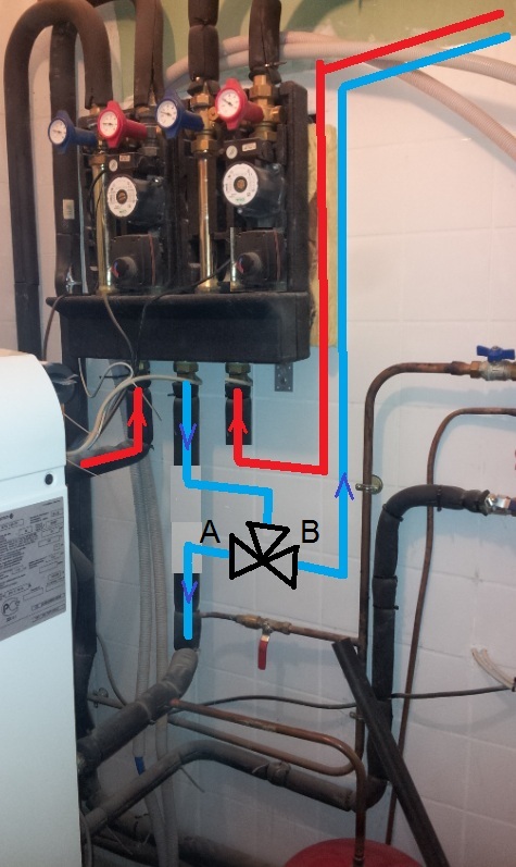
But as long as the need is zero, no traffic to the transmitters and in this case, if you make a fire, it is necessary that the calories and the flow rate of the circulator of the insert go somewhere.
This is where the buffer tank loads.
Otherwise, it is necessary to control this valve at the opening only if there is a need for heating, and there we gain nothing compared to the other principle.

mi16man wrote:if the tank has 40 ° therefore loaded: opening of the zone valve I switch to "wood" mode and at the same time my heating requirement is zero !!
what is happening?
the balloon continues to charge? beyond its zone valve opening setpoint temperature?
I see what you mean in fact I do not switch "purely" from one system to another with this connection because the water from the radiators continues to return in part to the boiler?
whereas with your zone valve connection it is either "wood" or "boiler".
would it not be possible to use this surplus for DHW
With your regulation you will be able to proceed by priority heating or DHW but your interest will be to cut the boiler as soon as possible (from March-April) and to produce DHW only with Rotex and to make fire only in the evening for example .

Back to "Heating, insulation, ventilation, VMC, cooling ..."
Users browsing this forum : No registered users and 289 guests