Hi: I am looking for information about bubblers water dopaje system. can anyone help me in this research?
I try to get to the bubbler design efficient as possible.
The thank you box
Drawing for the bubbler water doping?
-
Christophe
- Moderator

- posts: 79295
- Registration: 10/02/03, 14:06
- Location: Greenhouse planet
- x 11028
There are no more effective bubblers than others. A bubbler is a bubbler.
But there are bubblers more or less adapted to the engine on which we put it.
My favorite alternative is the steam generator:
https://www.econologie.com/generateur-de ... -3735.html
https://www.econologie.com/forums/generateur ... vt668.html
https://www.econologie.com/forums/peugeot-20 ... t1610.html
0 x
Do a image search or an text search - Netiquette of forum

Christophe wrote:There are no more effective bubblers than others. A bubbler is a bubbler.
But there are bubblers more or less adapted to the engine on which we put it.
Not as sure as you, for a car, a large bubbler of several liters (> 2 or 3 liters?) Is very difficult to heat in addition to being more than cumbersome, with a large inertia / start-up time .. .... not sure it works that well.
In chai plus what post I gave this mini specifications (to improve of course)
Construction of a bubbler (for a car):
Conclusion volume , height, diameter inlets and outlets, positioning of the various pipes must be defined before starting the installation under the hood ..... space is a rare commodity and pipes too long (meters) to be avoided. For an equal volume of water, it is better to have a height> diameter.
Material choice: copper, stainless steel, brass, PVC, or scrap if you want corrosion problems.
Le volume of water can range from ladle 0.15 to 2 liters?.
In fact the more water there is, the more difficult it is to heat and heat quickly, to fit under the hood ..... master the chop etc ...
Le air volume above the water is certainly necessary (no testing above). In any case, a sufficient height of air above the water is necessary, so that any bubbles that may form, do not rise in the outlet piping and go to the reactor (height 10 cm?).
La temperature from 57 to 90 °? Too low 57 ° I have doubts about the efficiency, and too high 90 ° according to André the steam that comes out is no longer good.
If adjustable air inlet (diameter 2 to 6 mm approximately).
If air inlet not adjustable (If the restriction is made further in the circuit) diameter 10 to 15 mm?)
Bubble height dependent on the suction and the engine speed of the presence of a venturi etc ...
Low height, bubbling from low revs.
greater height (10 cm?), more efficient bubbling but at higher speed.
Bubble size in the bubbler, the finer the bubbles, the better it works, the greater the quantity of water carried (passage through a thin drilled disc (1 to 1.5 mm) with numerous holes (150 to 200) separated (not The size of the bubbles is closely linked to the diameter of the holes.
Air heating entering the bubbler. Does not change much in summer, the winter (not made these tests).
Air filtering:
If the air intake is not too close to the ground (<40cm) it is not compulsory. The bubbling cleans ..... and forms the mud at the bottom of the bubbler. A coarse grid is sufficient.
Heating of the bubbler:
1) - by direct exhaust gases (all slut, black water etc ..., incalculable water consumption).
2) - by the exhaust through a pipe (heating power to be adjusted, low inertia).
3) - by the coolant (excellent temperature regulation and operating stability, a little slower to start than solution n ° 2)
Water level:
- Electric (float), it is necessary to calm the swirls of braking etc ...
- Constant level such as automatic bleeding of central heating (extremely difficult to operate correctly, cannot manage pressure variations) Generally hangs open and overflows with air.
- Continuous supply by small pump and overflow return (when the water tank is located lower than the rest of the installation, more complicated but very safe)
Different tubing:
- coolant diameter (8 to 16 mm inside?) (avoid high points which can fill with gas make bleeding problems of the cooling circuit)
- The water inlet hose diameter 4 mm inside (without high points + filter)
- Steam outlet in copper or synthetic diameter (8 to 15 mm inside?) With an anti-splash deflector on braking, turning, etc.)
maintains / drain:
Possible cleaning of the mud / crystallizations which will deposit at the bottom of the bubbler.
Positioning bubbler:
- ideally below the intake level / height (anti-siphoning security).
- Short piping (anti cooling)
- Accessible for filling / maintenance.
- Not in the passenger compartment (boiling water security).
Making more small bubbles increases the electrification of the water droplets in the fog coming out of the bubbler. (Interpretation of documents given by Bob Isat).
0 x
Reason is the madness of the strongest. The reason for the less strong it is madness.
[Eugène Ionesco]
http://www.editions-harmattan.fr/index. ... te&no=4132
[Eugène Ionesco]
http://www.editions-harmattan.fr/index. ... te&no=4132
Nice detailed list.
with:
it is clear that it is a fine fogger, to be electrified with HT spark discharges, as in thunderstorm clouds, or with lots of whirlpools, rubbing the droplets against each other and against the air, on a long drive, like in thunderstorms.
with:
Making more small bubbles increases the electrification of the water droplets in the fog coming out of the bubbler
it is clear that it is a fine fogger, to be electrified with HT spark discharges, as in thunderstorm clouds, or with lots of whirlpools, rubbing the droplets against each other and against the air, on a long drive, like in thunderstorms.
0 x
dedeleco wrote:with:Making more small bubbles increases the electrification of the water droplets in the fog coming out of the bubbler
it is clear that it is a fine fogger, to be electrified with HT spark discharges, as in thunderstorm clouds, or with lots of whirlpools, rubbing the droplets against each other and against the air, on a long path, as in thunderstorms.
Are you also thinking of an assembly giving HT between the reactor body and the reactor rod? I can not imagine how it will not short circuit in less than two by killing the HT system ... a millimeter of air gap, more or less dirty water (conductive) that arrives in there in packages from time to time, a little crystallization ... If you have an idea of "reliable" assembly, I am interested.
Should we polarize? Is there an interest in putting the + or the - on the reactor rod?
Is it rather an alternative voltage? Frequency?
When the scale deposit inside the reactor is almost continuous, dry (hot), they may already be electrostatic discharges between the shell and the rod of the reactor ...
... as in the clouds of thunderstorms, or with lots of whirlpools, rubbing the droplets against each other and against the air, on a long journey, as in thunderstorms.
With a ladle, the annular space (rod envelope) of the reactor must realize it
0 x
Reason is the madness of the strongest. The reason for the less strong it is madness.
[Eugène Ionesco]
http://www.editions-harmattan.fr/index. ... te&no=4132
[Eugène Ionesco]
http://www.editions-harmattan.fr/index. ... te&no=4132
-
RV-P

- I understand econologic

- posts: 158
- Registration: 27/09/12, 13:07
- Location: Sainte-Marie (Reunion Island)
- x 10
- Hello !
- Having read "in full, in width and across" the excellent site devoted to the G-Pantone reactor (for tractors, without modification of the engine), I had the idea of a bubbler heated by gas from 'exhaust with the following characteristics:
* speed of heating for short journeys,
* regulation by a valve controlled by a calorstat (80-85 °),
* preheating of the intake air,
* simplicity of assembly (minimum intervention on a car).
- Here is the diagram:
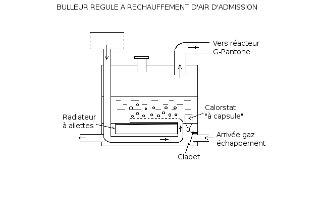
- Explanations:
* The finned radiator, glued under the double bottom, allows faster heating. It can easily be taken from an unusable amplifier.
* The calorstat is one of those non-adjustable models where a small rod comes out of the capsule when the temperature is reached. It is glued by a two-component paste (which I call "patafix") resistant to heat (300 °).
* I also chose to heat the intake air, again for faster reheating. Even the heating of the intake air is regulated by the calorstat (Note: the double bottom can be removed from below for maintenance and cleaning - although: the exhaust would be much "cleaner"! - and, for stability of the water level, the bubbler can be partitioned off by simply placed braces, without welding them).
- What do you think (Dedeleco's derogatory remarks are not welcome!)?
- Having read "in full, in width and across" the excellent site devoted to the G-Pantone reactor (for tractors, without modification of the engine), I had the idea of a bubbler heated by gas from 'exhaust with the following characteristics:
* speed of heating for short journeys,
* regulation by a valve controlled by a calorstat (80-85 °),
* preheating of the intake air,
* simplicity of assembly (minimum intervention on a car).
- Here is the diagram:
- Explanations:
* The finned radiator, glued under the double bottom, allows faster heating. It can easily be taken from an unusable amplifier.
* The calorstat is one of those non-adjustable models where a small rod comes out of the capsule when the temperature is reached. It is glued by a two-component paste (which I call "patafix") resistant to heat (300 °).
* I also chose to heat the intake air, again for faster reheating. Even the heating of the intake air is regulated by the calorstat (Note: the double bottom can be removed from below for maintenance and cleaning - although: the exhaust would be much "cleaner"! - and, for stability of the water level, the bubbler can be partitioned off by simply placed braces, without welding them).
- What do you think (Dedeleco's derogatory remarks are not welcome!)?
0 x
It's easier to just make things complicated than complicate simple things!
Hello RV-P
Just a few small remarks:
The radiator of the amplifiers is certainly made of aluminum and sticking it on steel (I suppose) in a hot, humid and acidic environment (exhaust gases) you are going straight to intense corrosion / rapid destruction problems. Soldering or brazing stainless steel or copper fins would last significantly longer and with better efficiency.
It lacks a little protection against chop on the steam outlet when braking / accelerating / turning, so as not to send a sip of floats in the pipe.
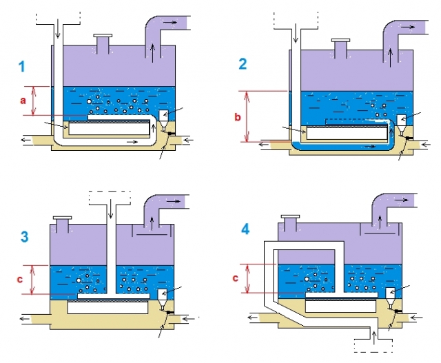
AMHA, the route of the air intake pipe must not be mounted like this (with a handle that descends lower than the level or the air escapes in the bubbler) diagram 1. The water column is larger and your bubbler can only aspire to a significantly higher engine speed (depression). When stopped, it will fill with water up to the top of the bubbler water level. Then you will need an even larger suction to get to suck diagram 2. (You can no longer drain the water that has accumulated in the base part). This assembly is extremely unstable in its operation (in addition the vacuum must move the water which moves by the chop ...)
A proposal in diagram 3 simpler, and another more efficient for heating water / air in diagram 4 which respect the siphon effect for a more stable operation.
RV-P wrote:- Having read "in full, in width and across" the excellent site devoted to the G-Pantone reactor (for tractors, without modification of the engine), I had the idea of a bubbler heated by gas from 'exhaust with the following characteristics:
* speed of heating for short journeys,
* regulation by a valve controlled by a calorstat (80-85 °),
* preheating of the intake air,
* simplicity of assembly (minimum intervention on a car).
- Here is the diagram:
- Explanations:
* The finned radiator, glued under the double bottom, allows faster heating. It can easily be taken from an unusable amplifier.
* The calorstat is one of those non-adjustable models where a small rod comes out of the capsule when the temperature is reached. It is glued by a two-component paste (which I call "patafix") resistant to heat (300 °).
* I also chose to heat the intake air, again for faster reheating. Even the heating of the intake air is regulated by the calorstat (Note: the double bottom can be removed from below for maintenance and cleaning - although: the exhaust would be much "cleaner"! - and, for stability of the water level, the bubbler can be partitioned off by simply placed braces, without welding them).
- What do you think (Dedeleco's derogatory remarks are not welcome!)?
Just a few small remarks:
* The finned radiator, glued under the double bottom, allows faster heating. It can easily be taken from an unusable amplifier.
The radiator of the amplifiers is certainly made of aluminum and sticking it on steel (I suppose) in a hot, humid and acidic environment (exhaust gases) you are going straight to intense corrosion / rapid destruction problems. Soldering or brazing stainless steel or copper fins would last significantly longer and with better efficiency.
It lacks a little protection against chop on the steam outlet when braking / accelerating / turning, so as not to send a sip of floats in the pipe.
AMHA, the route of the air intake pipe must not be mounted like this (with a handle that descends lower than the level or the air escapes in the bubbler) diagram 1. The water column is larger and your bubbler can only aspire to a significantly higher engine speed (depression). When stopped, it will fill with water up to the top of the bubbler water level. Then you will need an even larger suction to get to suck diagram 2. (You can no longer drain the water that has accumulated in the base part). This assembly is extremely unstable in its operation (in addition the vacuum must move the water which moves by the chop ...)
A proposal in diagram 3 simpler, and another more efficient for heating water / air in diagram 4 which respect the siphon effect for a more stable operation.
0 x
Reason is the madness of the strongest. The reason for the less strong it is madness.
[Eugène Ionesco]
http://www.editions-harmattan.fr/index. ... te&no=4132
[Eugène Ionesco]
http://www.editions-harmattan.fr/index. ... te&no=4132
-
RV-P
- I understand econologic
- posts: 158
- Registration: 27/09/12, 13:07
- Location: Sainte-Marie (Reunion Island)
- x 10
Flytox wrote:The radiator of the amplifiers is certainly made of aluminum and sticking it on steel (I suppose) in a hot, humid and acidic environment (exhaust gases) you are going straight to intense corrosion / rapid destruction problems. Soldering or brazing stainless steel or copper fins would last significantly longer and with better efficiency.
- It can be glued with an adhesive that resists corrosion and provides insulation between aluminum and stainless steel, while being heat conductive, especially if the aluminum is black anodized (electrical insulation). But your remark is correct. Welded fins will also do the trick!
 Ruse of Sioux: we can also crease the bottom sheet (between water and exhaust gases)! It avoids sticking or welding fins, while significantly increasing the exchange surface !!!
Flytox wrote:It lacks a little protection against chop on the steam outlet when braking / accelerating / turning, so as not to send a sip of floats in the pipe.
- I thought about it when I said this:
- And, for the stability of the water level (turns, brakes), the bubbler can be partitioned by crosspieces simply installed, without welding them.
- As in an ice cube tray, for example (the aluminum tubs with the zipper to release the ice cubes)!
- Thank you for the precision of the positioning of the air suction pipe which, indeed, fills with water and which must be "purged". Your diagram 4 is a great solution, but putting the pipe in the other direction. Like this, for example:
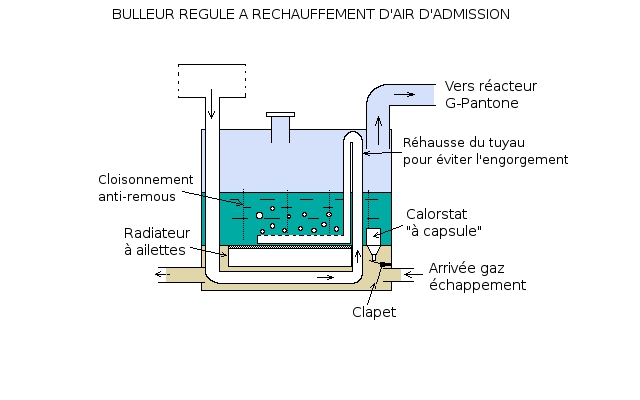
- Thanks for the details!
0 x
It's easier to just make things complicated than complicate simple things!
Back to "Special motors, patents, fuel consumption reduction"
Who is online ?
Users browsing this forum : No registered users and 190 guests