Following this "innovation" Water injection-motor-pantone / injection of water-misted-in-bmw-on-a-turbo petrol-t13753.html
I propose that we find and analyze the bmw or patents on this technology ... including understanding management: under what conditiokns injected water and how much. I have some ideas on the subject (acceleration, high loads ...)
Bon.commençons by finding the patent ...
BMW Patent injecting water in an engine
-
Christophe
- Moderator

- posts: 79287
- Registration: 10/02/03, 14:06
- Location: Greenhouse planet
- x 11024
-
Christophe
- Moderator
- posts: 79287
- Registration: 10/02/03, 14:06
- Location: Greenhouse planet
- x 11024
I have to find one first: EP2789839 System and method for water injection for an internal combustion engine published 15 / 10 / 14 for an initial deposit in 2013 under priority DE201310206102
http://worldwide.espacenet.com/publicat ... 9A2&KC=A2#
Search also: http://worldwide.espacenet.com/advanced ... cale=en_EP
Type "BAYERISCHE MOTOREN WERKE AG" in Applicant (s), "BMW" does not give much ... (only 800 patents ...)
BMW has installed more than 27 000 patents ...
Page bookmark EP2789839 (A2) - System and method for water injection for an internal combustion engine
Inventor (s): BÖHM MARTIN [DE]; KNIPS STEPHAN [DE] +
Applicant (s): BAYERISCHE MOTOREN WERKE AG [DE] +
Classification:
- international: F02B47/02; F02M25/03; F02M43/04; F02M69/04
- Cooperative:
F02B47/02; F02D41/0025; F02D41/3094; F02M25/03; F02M43/04; F02M69/046; Y02T10/121
Application number: EP20140156485 20140225
Priority number (s): DE201310206102 20130408
Also published as: EP2789839 (A3) DE102013206102 (A1)
http://worldwide.espacenet.com/publicat ... 9A2&KC=A2#
Summary:
A water injection system for an internal combustion engine (12) has first injectors (16), each containing a liquid directly into a combustion chamber (14) of the internal combustion engine (12) injecting and second injectors (24) each containing a liquid in a suction tube (20) before the injection of the combustion chamber (14).
It is provided with at least one between a fuel tank (38) and the first and second injectors (24) disposed fuel supply line valve (40) and between a water tank (48) and the first nozzles (16) located water supply line valve (52).
Valves (40, 52) are so switchable that the first nozzles (16) both in fluid communication with the fuel tank (38) and with the water tank (48) and the second nozzles (24) in flow communication with the fuel tank (38) can be brought.
Water is available in certain load ranges during the first injectors (16) is injected into the combustion chambers (14).
The fuel is a function of the load either by the first injectors (16) directly into the combustion chambers (14) of the internal combustion engine (12) or second injectors (24) in the suction pipe (20) Boards of combustion (14) in injected upstream.
Search also: http://worldwide.espacenet.com/advanced ... cale=en_EP
Type "BAYERISCHE MOTOREN WERKE AG" in Applicant (s), "BMW" does not give much ... (only 800 patents ...)
BMW has installed more than 27 000 patents ...
0 x
Do a image search or an text search - Netiquette of forum
-
Christophe
- Moderator
- posts: 79287
- Registration: 10/02/03, 14:06
- Location: Greenhouse planet
- x 11024
And 2ieme DE102012207907
http://worldwide.espacenet.com/publicat ... 07A1&KC=A1
Water injection system for injecting water to combustion engine of vehicle to suppress knocking combustion and Increase efficiency, HAS additive volume for Storing frozen water and connectable with rail injection by opening of valve
Summary:
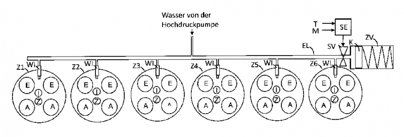
Edit by Remundo: Wasser von der Hochdruckpumpe: Water of [high-pressure pump]
http://worldwide.espacenet.com/publicat ... 07A1&KC=A1
Water injection system for injecting water to combustion engine of vehicle to suppress knocking combustion and Increase efficiency, HAS additive volume for Storing frozen water and connectable with rail injection by opening of valve
Summary:
The system has water injectors (W) arranged for the respective cylinders (Z1-Z6) of a combustion engine.
The water injectors are supplied with water at a high pressure fuel rail (EL).
A volume of additive (ZV) for storing frozen water can be connected to the high-pressure injection manifold by opening a switching valve (SV).
The volume of additive comprises a spring loaded piston (K), which pushes the water stored in the volume of additive after defrost by opening the valve from the volume of additive in the fuel rail high pressure.
Edit by Remundo: Wasser von der Hochdruckpumpe: Water of [high-pressure pump]
0 x
Do a image search or an text search - Netiquette of forum
-
Christophe
- Moderator
- posts: 79287
- Registration: 10/02/03, 14:06
- Location: Greenhouse planet
- x 11024
Good is the google translation here ... the original documents in German ...
a) http://worldwide.espacenet.com/publicat ... cale=en_EP
b) http://worldwide.espacenet.com/publicat ... cale=en_EP
a) http://worldwide.espacenet.com/publicat ... cale=en_EP
b) http://worldwide.espacenet.com/publicat ... cale=en_EP
0 x
Do a image search or an text search - Netiquette of forum
-
Christophe
- Moderator
- posts: 79287
- Registration: 10/02/03, 14:06
- Location: Greenhouse planet
- x 11024
Good translation google's still more comprehensible here is the translation EP2789839
Scheme (for pins in the description):
Another scheme is related to the patent (Interestingly, an operating curve !!)

Scheme (for pins in the description):
Another scheme is related to the patent (Interestingly, an operating curve !!)
DESCRIPTION EP2789839
[0001]
The invention relates to a system and method for water injection for an internal combustion engine.
[0002]
In internal combustion engines, especially gasoline engines for motor vehicles, an injection of water in addition to the influence of the manipulation of low actual fuel, for example by a cooling effect.
It has been found that knocking combustion can be suppressed, and increase the combustion efficiency and therefore the power and the fuel consumption can be reduced.
[0003]
The object of the invention is to optimize an injection of water.
[0004]
This is possible with a water injection system for an internal combustion engine having first fuel injectors each having a liquid injection directly into a combustion chamber of the engine, and second injectors of each injecting a liquid into a pipe upstream of the combustion chamber.
There, a fuel supply line valve is at least provided which is disposed between a fuel tank and the first and second injectors, and a water supply line valve which is arranged between a tank water and the first nozzles.
The fuel supply valve and the water supply valve are so switchable that the first nozzles can be brought into flow communication with the fuel tank, both in fluid communication with the fuel tank and with the water storage container and the second nozzles.
In this way, the water of the internal combustion engine injection may be, within certain ranges of load or operating conditions provide directly in the combustion chamber, optionally in admixture with the fuel.
In addition, this system allows independent of the water injection, the fuel supply to two ways, one being a direct way of the first injector directly into the combustion chamber and from each other by a injection manifold before the combustion chamber, the fuel is mixed with air introduced.
The system of the invention thus optimizes the performance and fuel consumption over the entire engine operating range.
[0005]
If the fuel is injected through the secondary injectors and water in the first injectors, the injection timing of the injection of water may be varied and as regards the time of fuel injection of be moved.
[0006]
The first nozzles is preferably an upstream high pressure pump which is engageable through the fuel supply line valve of the fuel tank and above the feeder valve water to the flow connection into a water reservoir.
The high pressure pump advantageously corresponds to the usual high-pressure fuel pump of a direct injection system, which is used to generate the injection pressure required for the first injectors.
Water and fuel may be mixed before or in the pump and the mixture is injected.
It is also possible, when none of the fuel injectors via the first to provide support only water with the high pressure pump.
[0007]
The water supply line valve is preferably a metering valve through which the injection of water to a predetermined maximum flow rate can be adjusted freely.
In this way one gains another variable parameter that can be used to optimize the combustion.
[0008]
The injection pressure required for secondary injectors can be obtained by a high-pressure pump upstream of the fuel pre-feeder pump usually already, which is usually a part of the direct injection system.
[0009]
To carry water from the water tank, an additional water pump between the water tank and the water supply line valve is preferably connected, promotes high pressure water pump.
[0010]
The fuel supply valve, the water supply valve and the water pump are preferably connected by a control unit as required, so that the control unit may advantageously also order the second nozzles.
The control unit is for example connected to an electronic motor of the internal combustion engine or integrated therein.
[0011]
In a method according to the invention for the injection of water for an internal combustion engine is only available in certain areas or load
Injected modes of operation of the water of the internal combustion engine in the first injectors in the engine combustion chambers and the fuel depends on the load range or
Mode of operation of the other of the first injectors directly into the engine combustion chambers or the second nozzles in the intake manifold, and more precisely in a suction pipe directly upstream of the combustion chambers, injected.
This method can also be implemented with a system as described above.
[0012]
The fuel injection is preferably carried out at the same time exclusively in either the combustion chamber or exclusively in the suction line, but not in both.
The injection of water, however, preferably always takes place in the combustion chamber and not in the suction pipe, but it can, depending on the range of internal combustion engine or of their mode of operation load to be suspended.
[0013]
For example, in a first load range or
engine operating mode combustion is injected, no water, and the fuel can be injected only by the first nozzles in the combustion chambers.
This mode of operation is the cheapest to an engine cold start or the regeneration of a catalyst, ie in cases where heating of the engine or the generation of the desired high temperature of the exhaust gas.
[0014]
In a second load range, which lies in particular in a medium speed range below the fully charged, no water is preferably injected and the fuel is injected only through the injectors in the second pipe respective suction.
This second load range may be found in load of the internal combustion engine, for example at least 4000 1 / min and less than about 200 nm (or less than 100 Nm / liter displacement).
[0015]
Is in a third load range, in particular in a medium speed range is substantially fully charged, while the water is preferably injected through the first nozzles in the combustion chambers and the fuel is injected only through the second nozzles in the suction pipe.
This third load range, for example, less than 4,000 1 / min and 200 Nm
[0016]
(Or about 100 Nm / liter) are located on the engine.
In this range, the cooling effect is desired by the injected water and ensures z.
IE for an increase in internal combustion engine performance.
The timing of the injection of water can be compensated during the engine cycle with respect to the fuel injection timing.
[0017]
Located in a fourth load range, particularly in a high speed range is substantially fully charged, the water and fuel through the first nozzles may be injected into the combustion chambers.
This fourth load range may, for example above 4000 1 / min and greater than about
150 Nm (approximately 75 Nm / liter) are the engine.
[0018]
The figures above are of course a function of the motor and can vary the internal combustion engine of the internal combustion engine.
In principle, we recommend high-speed injection of water and areas with high load, where the cooling effect is advantageous.
[0019]
The invention is described below using an example of embodiment in reference to the accompanying drawings.
In the drawings:
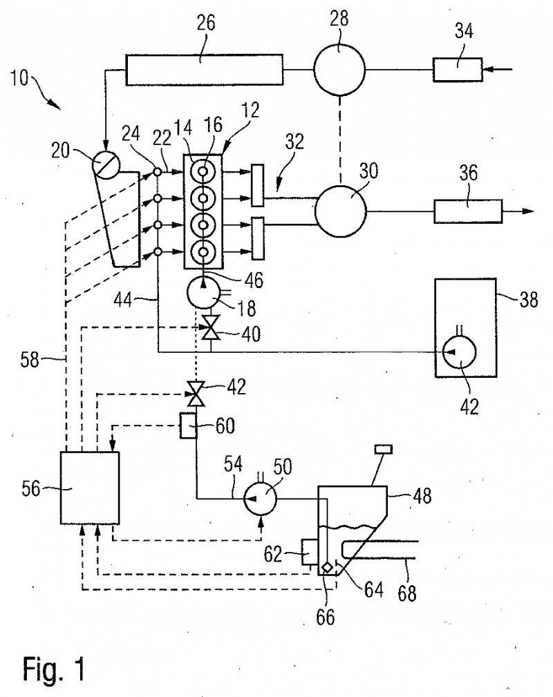
FIG 1 is a hydraulic schematic diagram and electronics of a system according to the invention for the injection of water; and
FIG 2 is a schematic representation of the injection of water and of fuel in different load ranges depending on a method of the invention for the injection of water.
[0020]
FIG 1 10 schematically illustrates a system for the injection of water to a 12 internal combustion engine, wherein the internal combustion engine to 12 in addition to water and conventional fuels or a mixture of water may be mixed with other liquids.
In this example, the combustion engine 12 is a gasoline engine and the fuel is gasoline.
[0021]
Normally, the amount of water injected is less than the amount of injected fuel.
[0022]
12 the internal combustion engine has a plurality of combustion chambers 14, in each of which a not shown plunger is moved for producing the drive energy.
Each of the combustion chambers 14 is in direct flow communication with a first 16 injector, the liquid which is supplied from a high-pressure pump 18, 14 is injected into the combustion chamber.
The high pressure pump generates 18 such a pressure to 200 250 bars.
[0023]
14 the combustion chamber is also provided for the combustion of fuel through a 20 suction pipe, a gas mixture, wherein a separate suction line leads to each of 22 14 combustion chambers.
At each of the Saugrohrabschnitte 22 another, second 24 injector is provided which can inject a liquid in the suction pipe before the 22 14 combustion chamber.
[0024]
10 in the system shown in FIG 1, the internal combustion engine 12 is provided with a turbocharger so that the compressed air, optionally mixed with the recirculated exhaust gas is introduced into the suction pipe 20.
The compressed feed air is cooled in a cooler 26, which is a fluid 28 downstream compressor.
28 the compressor is driven by a turbine in the 30 32 exhaust system.
The feed air flow is controlled in known manner by a mass flow meter of 34 air.
[0025]
32 in the exhaust system, one or more 36 gas processing units are provided here, for example, conventional catalysts or particulate filters absorb pollutants of the exhaust gases.
[0026]
fuel is the high pressure pump and the second 18 24 injectors fed from a fuel tank 38.
Means connected to the fuel tank 38 fuel line branches into a conduit of 44 fuel, resulting in the second 24 injectors and a driving 46 fuel leading to the high pressure pump and the first 18 16 injectors.
40 a valve, which is arranged in the fuel passage 46 upstream of the high pressure pump 18, turns off the fuel flow to the first injectors Sixteenth
[0027]
The injection pressure to the injectors 24 seconds is here produces a single fuel supply pump pumps fuel 42 38 the fuel tank and the high pressure pump 18.
[0028]
Injection through the second 24 injectors is controlled by 24 valves of the injectors.
It would also be possible to use in the fuel line of 44 38 fuel tank for the latter 24 injectors or another valve to place the valve at the junction 40 fuel lines 44, 46 and, for example, as a form of valve 3 way / 2 positions in a fuel flow to release either the high pressure pump 18 or 24 seconds injectors or nearby.
[0029]
A water storage tank 48 is connected by a water feed pump 50 and a water supply line valve 52 54 in a water supply line of the high pressure pump 18.
The water supply line valve 52 is formed as a metering valve, so that can be changed, the flow of water to the 18 high pressure pump and above, the amount of water spray.
The necessary pre-feed may be adjusted by means of the feed pump 50 water, this can be,.
Producing such a pressure of about 1 10 to bars.
The water tank 48 for example, has a volume of 10.8 liters.
[0030]
Control of the second 24 injectors, where applicable, the first 16 injectors, the fuel supply line valve 40, the water supply line valve and the pump 52 50 water is taken by a unit here 56 of control that can communicate via 58 control lines with these components (in FIG 1 for reasons of clarity, only one of the lines with reference numerals).
[0031]
The control unit also receives information 56 from 60 a pressure sensor disposed upstream of the water supply line valve 52 in the supply line 54 water, and a sensor 62 temperature measurement the temperature of the water in the water tank 48.
64 a level sensor monitors the water level in the tank 48 and also informs the control unit 56e
[0032]
The entrance to the 54 water supply line is here protected by a 66 filter which filters contaminants from water.
[0033]
Optionally, a 68 heater is provided for heating water in the water tank 48 to prevent this at low ambient temperatures to freeze thawing or at low ambient temperatures when starting the vehicle.
The heating here is also controlled by the control unit 56.
[0034]
10 the system can be switched so that the fuel is injected through either the first high-pressure injectors 16 14 directly in the combustion chambers or low pressure alternatively through the second nozzles in the 24 22 Saugrohrabschnitte and thence 14 air flow combustion chambers provided 14 enters the combustion chambers.
[0035]
In this example, either the first 16 fuel injectors or the second injectors 24 is provided.
The choice of fuel injection is, as will be described below, depending on the load range or in the operating mode wherein the engine operates 12.
[0036]
About 54 water water supply can be mixed with direct injection on 16 first injectors in fuel combustors 14.
The mixing takes place directly in the high pressure pump 18 or in a feed line directly upstream of the high pressure pump 18
The interconnection is made such that the water also passes to the high pressure pump when the 18 40 valve fuel supply line is closed and the fuel is injected only through injector 24 seconds in the 22 Saugrohrabschnitte .
In this case, it is also possible that the time of the injection of water to be chosen so as to not simultaneously carried out with fuel injection.
[0037]
Water injection is activated in some areas charge where improved performance can be achieved through the water supply.
In addition, the water supply is turned off when the level indicator 64 at a low level and the 62 temperature sensor at a low temperature in the water tank 48 reports in which there is a risk of freezing.
[0038]
FIG 2 shows how the injection of water and fuel in the different ranges of 12 inside the combustion engine of the load may be varied through the 10 system.
[0039]
Examples are four loading zones or
listed modes.
The details of each of the load ranges are naturally variable at the discretion of the expert.
[0040]
Injection via the first injectors 16 is marked with a "B", via the second injection injectors 24 having an "S".
[0041]
In a first load range or
operating mode I, which corresponds to a cold start of the internal combustion engine, but also alternately during operation of the motor vehicle, a state in which a regeneration of exhaust gas treatment facilities must be performed 36, fuel is injected only through the first injectors in 16 14 combustion chambers.
There is no drainage.
In these operating modes, a fast heating 12 internal combustion engine and a high temperature exhaust gas is desired.
[0042]
II in a second load range, which is in a medium speed range and a torque less than the full load of 12 internal combustion engine (in the example of Figure 2, below about 4000 1 / min and less than about 200 nm), as there is no water injection, fuel but completely injected by injectors 24 seconds in the 22 14 Saugrohrabschnitte before the combustion chambers.
The fuel supply line valve 40 44 in the fuel line is closed.
18 high pressure pump can be disabled in this case.
[0043]
In a third load range III, which is also in a medium speed range, but at a higher load, particularly at full load is located (in the example of FIG 2 below etwa4.000 1 / min and a torque more than about
200 Nm), the fuel injection continues to be carried exclusively over the second 24 22 Saugrohrabschnitte injectors in the front of the combustion chamber 14, but it will at the same time, water is injected through the first injectors 16 14 in the combustion chambers.
Water is now funded by the feed pump 50 water, the water supply line valve 52 and the high pressure pump 18 48 the water tank to the first 16 injectors and injected with a pressure 14 high injection into the combustion chambers.
There may be a cooling effect and thus affect combustion in the chambers of positive 14 combustion.
[0044]
In a fourth load range IV finally, here at high speed and preferably also at full load is located (in excess of about 4000 1 / min and higher torques about 150 nm), finally, the injection water through the first 16 injectors is maintained, the fuel injection changes However, 24 injectors seconds to the first injectors Sixteenth
Fuel and water are mixed before or during the high pressure pump 18.
The amount of water injected is determined by controlling the flow of water through the supply line through the valve 52 56 control unit.
The mixture of water and fuel is injected during the first 16 14 injectors in the combustion chambers.
[0045]
The amount of water may be injected z.
B. vary in load ranges within a certain framework to set the optimal combustion process.
Last edited by Christophe the 20 / 02 / 15, 00: 41, 1 edited once.
0 x
Do a image search or an text search - Netiquette of forum
-
Christophe
- Moderator
- posts: 79287
- Registration: 10/02/03, 14:06
- Location: Greenhouse planet
- x 11024
And of course the corresponding claims (this is the "heart" of the patent)
EP2789839 CLAIMS
1.
water injection system for an internal combustion engine (12) having first nozzles (16) each containing a liquid directly into a combustion chamber (14) of the internal combustion engine (12) injecting and second injectors ( 24) each containing a liquid in a suction tube (20) before the injection of the combustion chamber (14)
with at least one between a fuel tank (38) and the first and second injectors (24) disposed fuel supply line valve (40) and
a between a water tank (48) and the first nozzles (16) arranged water supply line valve (52)
wherein the fuel supply line valve (40) and the water supply valve (52) are switchable so that the first nozzles (16) can be brought both in fluid communication with the reservoir fuel (38) and with the water tank (48) and
the second nozzles (24) may be placed in flow communication with the fuel tank (38).
2.
Is connected upstream system according to claim 1, characterized in that dassden first injectors (16) a high pressure pump (18) by the fuel supply line valve (40) with the fuel tank (38) and through the water supply line valve (52) with the water tank (48) can be brought into flow connection.
3.
The system of claim 2, characterized in that the water supply line valve (52) is a metering valve, through which the injection of water at a predetermined maximum flow rate can be adjusted freely.
4.
System according to one of the preceding claims, characterized in that the high-pressure pump (18) upstream of a fuel supply pump (42) is provided, the injection pressure for the secondary injectors (24) produced.
5.
System according to one of the preceding claims, characterized in that a water supply pump (50) between the water tank (48) and the valve driving water supply (52) is connected, encourages water to the high pressure pump (18).
6.
A method for injecting water for an internal combustion engine, in particular for operating a system according to any preceding claim, wherein only in some internal combustion engine ranges (12) of water during of first nozzles (16) charge is injected into the combustion chambers (14) of the internal combustion engine (12) and
Fuel according to the load either by the first injectors (16) directly into the combustion chambers (14) of the internal combustion engine (12) or second injectors (24) in a suction pipe (20) upstream of the combustion chambers (14) is injected.
7.
The method of claim 6, characterized in Thata a first load range and in particular at starting of the internal combustion engine (12), no water is injected and the fuel is injected only through the first nozzles (16 ) in the combustion chambers (14).
8.
A method according to one of 6 and 7 claims, characterized in Thata a second load region lying in particular in a medium speed range lower than the full load, no water is injected and the fuel is injected only by the intermediate second injectors (24) in the suction pipe (20)
9.
A method according to one of claims to 6 8, characterized in Thata a third load region lying in particular in a medium speed range is substantially fully charged, the water in the first injectors (16) in rooms combustion (14) is injected and the fuel exclusively via the second injectors (24) is injected into the suction pipe (20).
10.
A method according to one of claims to 7 10, characterized in Thata a fourth load region lying in particular in a high speed range is substantially fully charged, water and fuel through the first injector (16) in the combustion chambers (14) are injected.
0 x
Do a image search or an text search - Netiquette of forum
-
Christophe
- Moderator
- posts: 79287
- Registration: 10/02/03, 14:06
- Location: Greenhouse planet
- x 11024
Same for the 2ième (no other scheme):
DESCRIPTION DE102012207907
[0001]
The invention relates to a water injection system for an internal combustion engine with high pressure water injection line.
[0002]
It is known to inject into a combustion engine of water to suppress the knocking combustion and thereby increase the effectiveness or performance.
For this, the water is provided with an injector in the intake manifold or directly injected into the combustion chamber or together with the fuel to the engine of the motor.
The water is usually taken from a tank and metered amount of water with a pulse valve.
[0003]
For example, a water injection system is provided which comprises a high-pressure fuel rail, is stored in the high-pressure water (similar to a rail fuel injection system common).
The high-pressure fuel rail is used for supplying common water injectors, each water injector is associated with a particular cylinder.
Each water injector comprises, for example a solenoid valve, which is controlled by a control unit.
Water is then injected into the cylinder combustion chambers through water injectors.
[0004]
In such a water injection system, there is a danger that at low temperature in the high-pressure fuel rail gel stored water which results in increase in volume loss in the injection system 'water.
[0005]
It is an object of the invention to protect such water injection system against damage caused by freezing of the water stored in the high-pressure fuel rail.
[0006]
The object is solved by the features of the independent claim.
Advantageous embodiments are described in the dependent claims.
[0007]
The water injection system of the invention for the injection of water for an internal combustion engine comprising at least one water injector for each engine cylinder.
In addition, a high pressure fuel rail is provided through which water injectors are supplied with water.
The system further comprises an additional volume for containing the frozen water and a valve (eg a solenoid valve), the additional volume of the high-pressure fuel rail by opening of the valve is connected.
[0008]
The additional volume can accommodate an increase in volume due to the formation of ice at low temperature with the valve open in case of freezing water stored in the high-pressure fuel rail.
Therefore, the pressure is reduced with respect to a high-pressure fuel rail without adding bulk, so that injury is avoided in the water injection system.
[0009]
For example, the additional volume capacity in the range of about about 14 30% of the system's recording capacity high pressure of the high pressure pump, through the high fuel rail pressure to the injectors (regardless of additional volume), especially about 20%.
The water expands when frozen about 1 / 7, about
14%.
The additional volume must have at least a capacity of about 14% of the capacity of the high pressure system.
[0010]
Preferably, the valve is closed during normal driving, so that the additional volume is separated from the high-pressure fuel rail.
The additional volume of a spring-loaded piston that is leading to unwanted oscillations and pressure pulsations in the fuel rail.
Furthermore, the additional volume would otherwise be emptied again displaced persons after the engine must include ice water.
[0011]
In the case of implementation of the engine by the driver and / or in the case of the falling below or reached (on the basis of a higher temperature) to a certain temperature, the valve is then opened to so the extra volume to contain frozen water is prepared.
[0012]
At low ambient temperature and allows you to relax, preventing damage by switching the valve, the high pressure system.
[0013]
It is advantageous for the water injection system comprises means for compensating the additional volume.
For example, the additional volume comprises a spring biased plunger.
The piston is suitable, for example, to squeeze in the additional volume of water stored after thawing with open valve from the complementary volume in the high-pressure fuel rail.
Thus, it can be emptied by the spring piston and the engine restart after thawing without pressure buildup system through the high pressure pump, the additional volume.
It is advantageous, then, if the additional volume to empty the water injector at least one, preferably all the water injectors are open.
Advantageously, according to grow out of the water stored closed the valve of additional volume.
[0014]
Furthermore spillage of additional volume in water can be removed from additional volume through the spring piston when the engine is stopped by the driver, to ensure that the additional volume for volume of the recording is available .
This process can be triggered by the driver's side actuation of the operating element for stopping the engine.
The removal of water from the auxiliary volume can be performed as follows: The injectors should preferably be injected after actuation of the driver's side of the operating element for stopping the engine during a phase short latency engine normal amounts of water, so that the combustion during the monitoring phase is not disturbed.
At the same time, the high pressure water pump is preferably no more than substantially promote water, so that the system pressure is reduced.
In parallel, open the additional volume Preferably, the valve switching, so that the piston emptied by the force of the additional volume of spring.
In this state, the engine can be turned off.
The complete Abstellprozedur that when parking the vehicle may depend on the ambient temperature, so that, for example, only the additional volume is cleared so the need for extra capacity is needed because of ice formation for example, below a certain ambient temperature.
[0015]
Alternatively or in addition, can be verified by an additional sensor if the volume is essentially no added water, for example by changing the position of the piston is checked.
[0016]
The opening and closing of the valve is preferably controlled by an electronic control device that is integrated for example in a motor control unit.
[0017]
The invention is described below using the accompanying drawings using an exemplary embodiment.
[0018]
fig. 1 schematically shows an embodiment of the water injection system according to the invention.
FIG 1 that parts of the high pressure region is indicated, the low-pressure circuit is not shown.
The water injection system comprises a high pressure fuel rail EL, in water, which is fed by a high pressure pump is stored under high pressure.
Each cylinder of the example shown, a six-Z1 Z6 cylinders comprises at least one water WI injector for injecting water into the combustion chamber of each cylinder Z1-Z6.
The water injectors are supplied by the high pressure tablespoons common water fuel rail.
[0019]
In addition, each cylinder has a spark plug Z-Z1 Z6 and at least one intake valve and at least one exhaust valve E A.
[0020]
To protect the system against damage caused by freezing of the water, a ZV additional volume is located in the fuel rail high pressure EL, which may take the case to the increased volume during freezing located in the high-pressure fuel rail icy water water.
For example, the ZV extra volume and a capacity of about 20% of the capacity of the high pressure system (without taking into account the additional volume).
ZV additional volume has a piston spring K.
[0021]
ZV additional volume is separated from the high-pressure circuit by a safety valve SV of the high pressure circuit.
[0022]
The SV of the safety valve is controlled by a control unit SE.
The control unit SE takes such a signal indicative of the temperature T of the temperature of the environment of the vehicle, and a motor signal M, which indicates whether the internal combustion engine has been turned on or off by the driver , on the contrary.
Alternatively or in addition, information on the operation of the driver's door can be used to control the safety valve SV.
In the case where the target motor signal M that the internal combustion engine has been stopped by the driver, and a critical temperature that is less than or less equal to a threshold value Ts (for example, Ts = 10 ° C) the safety valve SV is opened so that the additional volume of ZV with the high-pressure fuel rail is connected EL and ZV switching volume accommodating the increase in volume due to ice formation.
[0023]
Is optional is also conceivable that the driver's side the first engine, the Abstellprozedur described above for the removal of any gelangtem notification in additional water volume ZV additional means of ZV volume of spring piston K is made so ZV ensure that the additional volume available for volume expansion.
Abstellprozedur this is performed, for example, only below a certain threshold value for the room temperature.
If the vehicle is stationary, for example, after draining the engine, the switching valve SV is closed to allow the injection of water is ready to restart the engine in conditions not critical immediately after starting.
Otherwise, the switching valve SV must remain open below a critical temperature or to be opened again, so that the ZV additional volume in the high pressure fuel rail is connected EL and volume ZV switching can receive the volume increase due to ice formation.
[0024]
After starting the engine system and thawing of the ZV additional volume by the piston spring with open K SV safety valve is essentially emptied by opening the WI water injectors, without significant accumulation pressure by the high pressure pump.
Thereafter, the safety valve SV from the control device is closed SE.
For example, for this purpose the motor M signal monitor and a period of time after switching the motor M signal during engine startup, the safety valve SV is closed.
The time period, for example, depends on the temperature signal ST.
[0025]
After closing the safety valve of the auxiliary volume ZV SV can be used when a new engine shutdown if necessary to re-expansion of the water.
0 x
Do a image search or an text search - Netiquette of forum
-
Christophe
- Moderator
- posts: 79287
- Registration: 10/02/03, 14:06
- Location: Greenhouse planet
- x 11024
DE102012207907 CLAIMS
1.
water injection system for injecting water for an internal combustion engine, comprising:
- At least one water injector (WI) per cylinder (Z1-Z6) of the internal combustion engine,
- A high-pressure fuel rail (EL), are provided by water injectors (W) with water,
- A valve (SV) and
- An additional volume (ZV) for receiving the frozen water, which is connected to the high-pressure fuel rail (EL) by opening valve (SV) is connected.
2.
water injection system according to claim 1, wherein the water injection system is disposed in the case of engine placement by the driver and / or in the case of posing or reach a certain temperature to open the valve (SV).
3.
water injection system according to one of the preceding claims, wherein the additional volume (ZV) comprises a spring loaded piston (K).
4.
water injection system according to claim 3, wherein said spring piston is fitted in the additional volume (ZV) of the stored water after thawing when the valve (SV) from the additional volume (ZV) in the high-pressure fuel rail (EL) to the press.
5.
water injection system according to one of the preceding claims 3-4, wherein the water injection system is introduced, after having pushed out of the water stored in the additional volume (ZV) for close the valve (SV).
6.
water injection system according 3-5 claims in which the water injection system is set up, the next possible stop motor driver in the supplementary volume (ZV) has water volume additional (ZV) using the spring piston (K) to remove.
7.
water injection system according to any preceding claim, wherein the additional volume (ZV) has a capacity in the range of about about 14 30% of the capacity of the water injection system without the additional volume (ZV).
0 x
Do a image search or an text search - Netiquette of forum
-
Christophe
- Moderator
- posts: 79287
- Registration: 10/02/03, 14:06
- Location: Greenhouse planet
- x 11024
Small note in passing: the 1er patent seems more important because it was published in EP (EUROPE) which does not appear the case of 2ième ...
0 x
Do a image search or an text search - Netiquette of forum

if it comes down, it's a common rail with water instead of fuel.
Practice for the Germans who do not need much to change the material they have already mastered largely on direct high-pressure fuel injection.
compared to the descriptive section of the BMW M4 there are differences (indirect injection, not individual injector on each cylinder).
It seems like the technical problem is the management of ice formation. Indeed, water relaxing cools and can form ice crystals. Also high pressure can turn a fresh liquid water ice.
it should not be easy to manage ... What are actually the advantages of high water pressure? It is sure that if we want to inject it directly to TDC eg one force to work in high-pressure ...
I think a low pressure (10 bar for example) with a fogger indirect injection will be a good compromise. And the choice of BMW prototype M4.
0 x
-
- Similar topics
- Replies
- views
- Last message
-
- 15 Replies
- 12666 views
-
Last message by Christophe
View the latest post
09/06/06, 11:24A subject posted in the forum : Water injection in heat engines: information and explanations
-
- 2 Replies
- 7725 views
-
Last message by MobyleX
View the latest post
28/01/05, 19:53A subject posted in the forum : Water injection in heat engines: information and explanations
Go back to "Water injection in heat engines: information and explanations"
Who is online ?
Users browsing this forum : No registered users and 88 guests