How to Repair a 12V battery charger?

And if they were repairing rather than throwing and change? Rediscover the pleasure of the repairs yourself. How to diagnose a problem or find spare parts? Repair itself is way to save money generally!
dirk pitt
Econologue expert
Econologue expert
posts: 2081
Registration: 10/01/08, 14:16
Location: isere
x 68


by dirk pitt » 18/10/13, 10:50

voltmetre in position AC 20V measure the voltage between the two golden "radiators".
you must have a voltage of the order of 17 or 18V
if not, the transformer is dead (or fuse upstream)
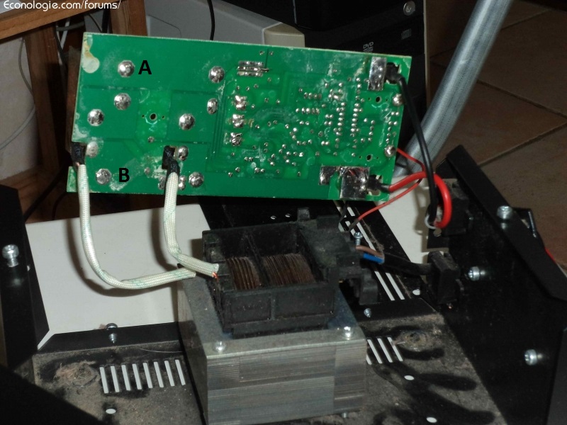
then, voltmetre in position DC 20V measure between points A and B
you must have a tension DC in the same order of magnitude.
If not, the rectifying diodes are dead.
if these two points are OK but still no output voltage. it can be more difficult.
Image
0 x
Image
Click my signature
BobFuck
I posted 500 messages!
posts: 534
Registration: 04/10/12, 16:12
x 2


by BobFuck » 18/10/13, 10:53

Too bad that the resolution of the images is too weak to be able to read the references. Can you post unscaled images somewhere?

It looks like the 2 heatsinks (big "U" in metal) are connected directly to the primary of the transformer. Therefore, measure the voltage between the 2 dissipators with a voltmeter, in "alternating voltage" mode. Attention, the 2 dissipators and the printed circuit must not touch anything of conductor (if not, short circuit), put thick cardboard under the circuit the time to take the measurement ...

Then you can measure the rectified voltage. On this photo :

https://www.econologie.info/share/partag ... U9pCar.JPG

It's on the circuit board between the 2 plots in the lower left corner and the upper left corner.

It looks like the charging current is switched by the mass of 2 big transistors.

A small cleaning (toothbrush and alcohol) would not be too much considering the amount of crap on the circuit ... lets dry well after ...
0 x
User avatar
chatelot16
Econologue expert
Econologue expert
posts: 6960
Registration: 11/11/07, 17:33
Location: Angouleme
x 264


by chatelot16 » 18/10/13, 11:55

it's real electronics

the rectifying diode are on big radiator, then all the current goes into 2 transistors without radiator ... sad design i would suspect these transistor to overheat

it would be necessary to note the reference of the integrated circuit (or to make a photo well framed above) because with the reference of the transformer one finds the shema which goes around in the doc of the integrated circuit
0 x
plaed
I learn econologic
I learn econologic
posts: 29
Registration: 28/02/22, 22:01
x 13

Re: How to repair a 12V battery charger?


by plaed » 28/02/22, 22:34

Hello,
Newly registered I don't know if I'm doing well to revive an old subject comparable to the one that brings me, or if it would have been better to launch a new one (which I can do if necessary).
So I have a very old battery charger (60s?) which no longer works (a priori does not deliver any charging current), and when I open it I have the impression that what seems to me to be a transformer almost liquefied (looks like some kind of paraffin has escaped from it and resolidified next to it).
I try to attach some photos to illustrate.
As it looks of a fairly simple design, I was wondering if it would be possible to repair it for a still reasonable cost, for example if replacing the transformer would be enough (assuming it is indeed the responsible, and where a replacement could be found, given the age of the item).
Thanks in advance for any insights!
IMG_0432.jpg
outer casing

IMG_0433.jpg
inside case

IMG_0436.jpg
front transformer

IMG_0437.jpg
transformer top

IMG_0435.jpg
other integrated appearance component

IMG_0434.jpg
input voltage selector on the right and ammeter on the left
0 x
plaed
I learn econologic
I learn econologic
posts: 29
Registration: 28/02/22, 22:01
x 13

Re: How to repair a 12V battery charger?


by plaed » 28/02/22, 22:36

I made a mistake on the last photo, it's the reverse of the output current selector that we see on the right side.
0 x
User avatar
Macro
Econologue expert
Econologue expert
posts: 6523
Registration: 04/12/08, 14:34
x 1641

Re: How to repair a 12V battery charger?


by Macro » 01/03/22, 06:49

Have you just checked the fuses that are used to vary the voltages and currents...
0 x
The only thing safe in the future. It is that there may chance that it conforms to our expectations ...
izentrop
Econologue expert
Econologue expert
posts: 13713
Registration: 17/03/14, 23:42
Location: picardie
x 1524
Contact :

Re: How to repair a 12V battery charger?


by izentrop » 01/03/22, 10:00

Hello,
You already need a multimeter to check all the elements: fuse, transformer, rectifier, galva, contacts of the oxidized wafer...
Then, with that old blunderbuss, if you don't monitor the charge with a multimeter, you're likely to shoot the battery. : Mrgreen:
0 x
plaed
I learn econologic
I learn econologic
posts: 29
Registration: 28/02/22, 22:01
x 13

Re: How to repair a 12V battery charger?


by plaed » 01/03/22, 20:20

Thanks to Macro and Izentrop for your feedback.
Yes I started with the 3 fuses, one seemed to me to be broken and I replaced it with "period" fuse wire, without change.
But at the opening when I saw all this kind of paraffin escaped from the transformer, I suspected that it was the cause of the malfunction.
I have a multimeter, but am a bit like a chicken who found a knife with this in my hands!
Well I know how to identify the fuses and the transformer, but I don't know what the rectifier, the wafer, etc. are, the galva is perhaps what I called the ammeter, or how to check them : Mrgreen:
But if you want to guide me a little I will try!
0 x
User avatar
Exnihiloest
Econologue expert
Econologue expert
posts: 5365
Registration: 21/04/15, 17:57
x 660

Re: How to repair a 12V battery charger?


by Exnihiloest » 01/03/22, 21:02

plaede wrote:Hello,
Newly registered I don't know if I'm doing well to revive an old subject comparable to the one that brings me, or if it would have been better to launch a new one (which I can do if necessary).
So I have a very old battery charger (60s?) which no longer works (a priori does not deliver any charging current), and when I open it I have the impression that what seems to me to be a transformer almost liquefied (looks like some kind of paraffin has escaped from it and resolidified next to it).
I try to attach some photos to illustrate.
As it looks of a fairly simple design, I was wondering if it would be possible to repair it for a still reasonable cost, for example if replacing the transformer would be enough (assuming it is indeed the responsible, and where a replacement could be found, given the age of the item).
Thanks in advance for any insights!
IMG_0432.jpg
IMG_0433.jpg
IMG_0436.jpg
IMG_0437.jpg
IMG_0435.jpg
IMG_0434.jpg


This stuff is extremely rudimentary. So it must be fixable... : Lol:

We see that there is no electronics apart from the gray block with fins, which seems to me to be a selenium rectifier, it is the weak link. It must be fired and replaced by a modern diode bridge, like https://www.amazon.fr/SODIAL-redresseur-monophase-KBPC5010-Nouveau/dp/B071PCWZDR/ref=sr_1_5 , to be screwed on the chassis for heat dissipation.
For the rest, if the transformer outputs the alternating voltage to its secondary and all the connections are good, it can only start again.
0 x
plaed
I learn econologic
I learn econologic
posts: 29
Registration: 28/02/22, 22:01
x 13

Re: How to repair a 12V battery charger?


by plaed » 02/03/22, 20:13

Exnihiloest wrote:
plaede wrote:
This stuff is extremely rudimentary. So it must be fixable... : Lol:

Thank you Exnihiloest, it's a bit the reasoning that I had naively made myself ...!

We see that there is no electronics apart from the gray block with fins, which seems to me to be a selenium rectifier, it is the weak link. It must be fired and replaced by a modern diode bridge, like https://www.amazon.fr/SODIAL-redresseur-monophase-KBPC5010-Nouveau/dp/B071PCWZDR/ref=sr_1_5 , to be screwed on the chassis for heat dissipation.
For the rest, if the transformer outputs the alternating voltage to its secondary and all the connections are good, it can only start again.


Before investing and attacking the replacement of the selenium rectifier, I might have an interest in checking the transformer.
But it would be very useful for me to have some indications on the terminals to be used for the control, and the operating mode (simple connection on the sector to feed, which measurement to carry out, tension or intensity?).

I am attaching a photo of each side of the transformer showing the cables leading from it.
Thanks in advance for your reviews!
Attachments
IMG_0439 (2) .jpg
side 2, outputs to requested output voltage setting
IMG_0438 (2) .jpg
side 1, outputs to load current setting
0 x


  • Similar topics
    Replies
    views
    Last message

Back to "failure, troubleshooting and repair: repair yourself? "

Who is online ?

Users browsing this forum : No registered users and 163 guests