Living in a small Alsatian village, I installed central heating 6 years ago in a house that was already built during the Molère era. I just changed my boiler. A Geminox T35. Mixed wood / fuel oil without DHW production.
I want to put a buffer tank so as not to waste the calories produced in excess by burning wood. Not being a specialist in the matter, I absolutely did not embark on complex calculations of pressure drops and other incomprehensible calculations for a neophyte.
I just want to know for the moment if I am
 or not !?
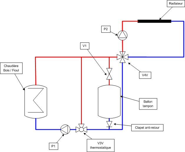
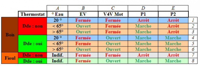
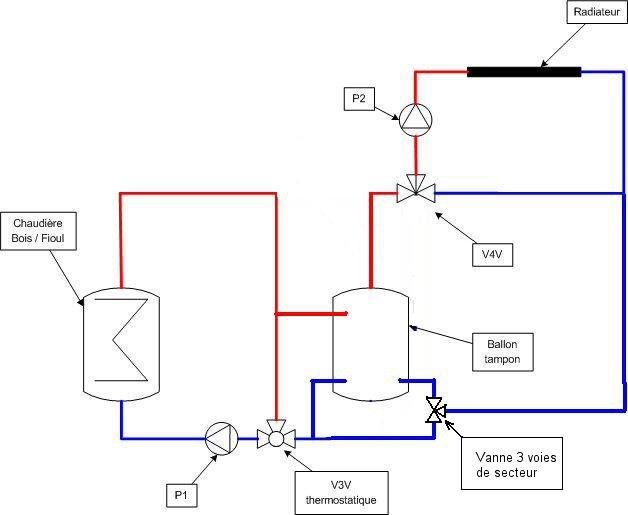
Connections
• VE
o The solenoid valve closes the arrival to the balloon as soon as the fuel starts. To avoid heating the balloon water with the fuel oil.
o It opens automatically at only 65 ° by a thermostat in order to heat the radiators as a priority.
• V4V
o The motorized 4-way valve managed by the boiler opens and closes on demand.
• P1
o The recycling pump operates continuously except when the water is at 20 °.
• P2
o The circulation pump in parallel with the V4V.
Apart from the ball, I am already in possession of all the equipment.
In advance, thank you for your comments and remarks.