Pictures and prices of our boiler installation wood stove

Heating, insulation, ventilation, VMC, cooling ... short thermal comfort. Insulation, wood energy, heat pumps but also electricity, gas or oil, VMC ... Help in choosing and implementation, problem solving, optimization, tips and tricks ...
Christophe
Moderator
Moderator
posts: 79332
Registration: 10/02/03, 14:06
Location: Greenhouse planet
x 11046

Pictures and prices of our boiler installation wood stove


by Christophe » 30/11/07, 20:35

Attention, assembly not to follow. The plan of the 2 version of this assembly is to be consulted here: heating-insulation / wood-boiler-new-schema-installation-DHW-and-pcs-t4589.html

Do not follow the V1.x editing plan which does not work well, but some photos and explanations remain valid. Reason: significant T ° variation and corrosion of the DHW tank exchanger, water-pumping-filtration/enameling-treatment-of-a-thermal-balloon-exchanger-t4461.html


Here are finally the photos of the deom that I just installed with which I have so much jabbered for a few weeks ... : Mrgreen: (see the topics: installation-assembly-boiler-or-wood-boiler-stove-t3494.html et diagram-wood-boiler-for-hot-water-and-heated-floors-t4266.html )

It is therefore self-installation and self-study to reproduce at your own risk :D

For the moment that a photo, I could take In Extremis before the battery is naze:
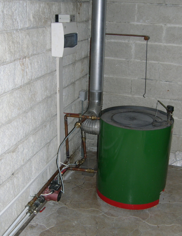
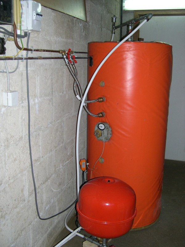
Image

We see :
- the solar differential control (above the electric box)
- the regulation box
- the thermal safety valve (follow the thermowell perpendicular to the boiler outlet)
- the control integrated in the boiler by thermostatic valve
- the circulator and its 2 union and isolation valves
- the beginning of PER pipes

The continuation with costing and the 1eres impressions of operation arrives in a few moments ...
Last edited by Christophe the 03 / 05 / 11, 14: 57, 7 edited once.
0 x
Christophe
Moderator
Moderator
posts: 79332
Registration: 10/02/03, 14:06
Location: Greenhouse planet
x 11046


by Christophe » 30/11/07, 22:54

Ah important thing to understand, here is the schematic diagram corresponding to this montage:

Image
0 x
Christophe
Moderator
Moderator
posts: 79332
Registration: 10/02/03, 14:06
Location: Greenhouse planet
x 11046


by Christophe » 30/11/07, 23:44

And here are the pictures:

A) General view of the boiler

The 2ieme regulation by electronic thermostat is fixed to the wall.

Image

B) Hot water inlet from boiler to buffer tank and / or heated floors

Image

See diagram to understand the valves, if I forgot the trap on the diagram.

C) General view of the buffer tank

Image

Comments:
- The electric box for the control valve is hooked to the wall (2 still missing moldings to fix the cable cleanly) it allows to cut the regulation when the boiler does not turn.
- you will notice the aquastat matching the colors of the balloon : Lol: : Lol:
- the braided hoses are the derivation for the ECS

D) Detail of the ball exit and the safety "group"

Image

Each valve is "easily" recognized since the opening of the valves corresponds to the plan.
The boiler return is via the curved pipe near the wall.

E) Connection to the heating circuit

Image

The modifications are the 2 copper tubes, one welded (return) and the other (go) mounted with a compression tee by olive (for ease of assembly especially, not easy to weld against a wall high).

The last tee on the return was added to keep the drain valve of the heating circuit, otherwise I could have left right as the go

F) Detail on the balloon

Image

From top to bottom:
- DHW diversion (mounted in inversion to improve heat exchange)
- mechanical thermometer for visual indication of the T ° of the buffer (probe at the bottom in the last thermowell)
- electrical resistance serving as a "plug", wiring is not provided
- aquastat controlling the solenoid valve

G) DHW bypass detail

Image

Completely made of copper-side compression fitting

H) Detail on buffer outlet

Image

Those who followed the pattern will understand :) And long live losses ...

I) Electric box of the boiler (see photo 1)

Image

Comparative regulation is done by a simple RESOL comparator (I do not know if it still exists)
I recovered a switch with a light indicating that the circulator is on.

J) Radiator view

Image
0 x
Christophe
Moderator
Moderator
posts: 79332
Registration: 10/02/03, 14:06
Location: Greenhouse planet
x 11046


by Christophe » 01/12/07, 10:49

Here is the costing (I have not yet the invoice of the different connections and PER, I have therefore estimated):

A) Boiler stove: 1500 €

It was a "proto" out of catalog, the following model which has 3 to 4kW more is worth more than 3000 € ... so we made a "deal" I think.

B) Solar balloon double glazed exchanger + regulation 2 points + 3 panels of 2.2 m² + circulator + expansion tank + valve 3 motorized track (used in electrovalve see photo, one side is blocked) all used (the balloon was built in 1979!): 1000 € at a friend heating. I have the 3 panels wired (more room on the roof :D ). I was lucky on this one when we know that a new double balloon exchanger can be charged up to 3000 €! : Evil:

C) Thermal safety valve: 120 € (pfff not given but good ...)

D) Different connections and safety devices (valve pressure, mano ...) including 20 m pipe 16 PER (it is PER quality, hence its price more expensive than those of Brico): 490 €

Total: 3110 € of material. For a wood boiler heating DHW and PCs. Labor and consumables extra (but apart from a little gas and tin there was nothing).
Last edited by Christophe the 10 / 12 / 07, 20: 00, 1 edited once.
0 x
User avatar
pef
I understand econologic
posts: 58
Registration: 02/10/07, 00:48


by pef » 01/12/07, 17:39

Beautiful realization !!

Small question, the calorstat that opens and closes the air is put on primary or secondary?
Can you take a picture closer?
0 x
fc89
I understand econologic
posts: 170
Registration: 20/10/07, 20:01


by fc89 » 01/12/07, 18:47

Hello,

Great job Christophe.
A small thing about the security of your DEOM (I have the eye, old reflex of a former member of the CHSCT).

In case of problem, power failure, pump failure the safety valve is connected to the output of the DEOM (I assume that the output is at the top of the DEOM),
this is not suitable, the cold water of the valve can not return from the DEOM since, it will be repulsed by the hot water.
In addition you risk creating a thermal shock very harmful for your DEOM.
Normally the cold water must come from the bottom to push the hot water (hoping that your PER does not melt), but you will need to add a check valve for the cold water to be well directed.
I speak in connoisseur, it has happened to me already, believe me the pipes begin to tremble and the noise would wake up a dead person.
I see the submariner is ready.
A+
0 x
Christophe
Moderator
Moderator
posts: 79332
Registration: 10/02/03, 14:06
Location: Greenhouse planet
x 11046


by Christophe » 01/12/07, 20:27

pef wrote:Beautiful realization !!

Small question, the calorstat that opens and closes the air is put on primary or secondary?
Can you take a picture closer?


Thank you this is my first installation :)

But I was not alone: ​​you helped me a lot :) (directly or indirectly)

For the calorstat I don't understand there is no primary or secondary everything is "primary" ... or are you talking about the turbo of the deom? In this case it is the regu is on the turbo.
0 x
Christophe
Moderator
Moderator
posts: 79332
Registration: 10/02/03, 14:06
Location: Greenhouse planet
x 11046


by Christophe » 01/12/07, 20:32

fc89 wrote:Hello,

Great job Christophe.
A small thing about the security of your DEOM (I have the eye, old reflex of a former member of the CHSCT).

In case of problem, power failure, pump failure the safety valve is connected to the output of the DEOM (I assume that the output is at the top of the DEOM),
this is not suitable, the cold water of the valve can not return from the DEOM since, it will be repulsed by the hot water.
In addition you risk creating a thermal shock very harmful for your DEOM.
Normally the cold water must come from the bottom to push the hot water (hoping that your PER does not melt), but you will need to add a check valve for the cold water to be well directed.
I speak in connoisseur, it has happened to me already, believe me the pipes begin to tremble and the noise would wake up a dead person.
I see the submariner is ready.
A+


1) For the wake of the dead yes it happened once, in fact I think I have a calibration problem with the safety valve :( It seems to trigger "too cold" ...

2) At the assembly level, the thermowell is rated hot but the injection of cold water is rated "cold". But indeed when the circulator is not running there is no reason for the water to pass through the boiler rather than through the circuit.

So you confirm what I was afraid of and I asked the heating engineer who sold me all the parts and who told me that like this it was "ok" ...

I asked him the question directly by suggesting to put a valve and he told me: "not necessary the water will be sucked from the hot side" ... so I did like this but ... it seems to be a bit messy anyway ... (it was the first problem I wanted to discuss with you after this presentation)
0 x
User avatar
pef
I understand econologic
posts: 58
Registration: 02/10/07, 00:48


by pef » 01/12/07, 20:40

Christophe wrote:For the calorstat I don't understand there is no primary or secondary everything is "primary" ... or are you talking about the turbo of the deom? In this case it is the regu is on the turbo.


Yes that's it ... on the Turbo so ....
I'm always interested in photography : Cheesy:


In the event of a power failure ... a battery and an inverter?
0 x
fc89
I understand econologic
posts: 170
Registration: 20/10/07, 20:01


by fc89 » 01/12/07, 21:06

Hi,

Pef wrote:
In the event of a power failure ... a battery and an inverter?

This can help in case of power failure, but if the circulator fails the battery will be of no use.

A thousand excuses Christophe, I had looked badly at the picture, the safety valve is well connected.
If you do not want to install a flapper, then just change the T copper to Y, which will direct the cold water to the DEOM.
The valve probe must certainly trip due to the heat of the DEOM or the flue.
Begin with a deflector.
On my installation, I have a pressure valve right out of the firebox, this valve is triggered at 2B while that of the oil boiler is tared at 3B, as I am sure that the cold water goes through the fireplace.
A+
0 x


  • Similar topics
    Replies
    views
    Last message

Back to "Heating, insulation, ventilation, VMC, cooling ..."

Who is online ?

Users browsing this forum : No registered users and 297 guests