Hello everyone
Possesseur since 3 years of a 508D 3L8 mercedes and a team of a vortex since 2 years I finally launch on pantone with friends we will equip 5 truck all 80CH 4 2L4 and my truck 3L8.
we will put a GVI and reactors of
stainless steel tube 316 L 350mm diam 21,3 ep 2,6
stainless steel rod 316 L 150mm diam 15
stainless steel rod 316 diam 6mm for the antechamber of 100mm and 50mm of relaxation angular space of the reactor 1,1mm
What questions remains such as the utliter of the tank at a constant level.
Is a drop by drop enough (gardening or hospital type).
Can the vortex replace the venturi?
Regarding the arrival of air ?.
What is the best way to return hot or cold air to the reactor inlet? when is there any chance of getting air in at the entrance of the GVI?
Thank you for your answers
@ soon
Mercedes truck 508D in water doping

Re: 508D mercedes truck in water doping
Hello timeisat Welcome to the club
To go directly into the subject, the annular space is 0.55 mm radius ... it's not enough it seems to me, the ratings that work are usually between 0.8 and 1.5 mm. Your loss of charge will be much too big.
You have the supporters and detractors of the constant level tank, for me it's a problem bag almost indem.dable to develop. By cons a drip system can work well.
No, it's not the same application, the vortex seeks to produce turbulence, the venturi is used to suck in the reactor. But we can perfectly fit both in series.
You have to try what works best in your setup / mount, the 2 solutions can work.
Give yourself the chance to try it, there are so many possible solutions ... that I would not pronounce a priori.
timeisat wrote:we will put a GVI and reactors of
stainless steel tube 316 L 350mm diam 21,3 ep 2,6
stainless steel rod 316 L 150mm diam 15
stainless steel rod 316 diam 6mm for the antechamber of 100mm and 50mm of relaxation angular space of the reactor 1,1mm
To go directly into the subject, the annular space is 0.55 mm radius ... it's not enough it seems to me, the ratings that work are usually between 0.8 and 1.5 mm. Your loss of charge will be much too big.
What questions remains such that the utliter of the tank at constant level .. Is that a drop by drop will be sufficient? (Type gardening or hospital)
You have the supporters and detractors of the constant level tank, for me it's a problem bag almost indem.dable to develop. By cons a drip system can work well.
Can the vortex replace the venturi?
No, it's not the same application, the vortex seeks to produce turbulence, the venturi is used to suck in the reactor. But we can perfectly fit both in series.
Regarding the arrival of air ?.
What is the best way to return hot or cold air to the reactor inlet?
You have to try what works best in your setup / mount, the 2 solutions can work.
when is there any chance of getting air in at the entrance of the GVI?
Give yourself the chance to try it, there are so many possible solutions ... that I would not pronounce a priori.
0 x
Reason is the madness of the strongest. The reason for the less strong it is madness.
[Eugène Ionesco]
http://www.editions-harmattan.fr/index. ... te&no=4132
[Eugène Ionesco]
http://www.editions-harmattan.fr/index. ... te&no=4132
Hi Flytox
Thank you for the remark we bought the stainless steel today so
316 21.3 2 tube and 316 14 1 rod so we have an annular space of 6mm now and then XNUMXmm rod always made of stainless steel.
The tank has a constant level is dropped however we wonder how to manage the air / water ratio for water no problem a properly adjusted drip system that will arrive on the gvi and air a hose connect air filter to the drip pipe. But how to manage the airflow ???? if you have to adjust it ???
Regarding the venturi is this essential? on the spad plan and some editing I do not see any venturi ...
thanks to Flytox and other members of your answers thank you
@ soon
0 x
There is no rule engraved in the marble for the diameter, length, material of the pipes, restrictions of passages on the different fluids etc ... but it is good to have adjustment to be able to look for the good configuration. For this, it is good that the air passages between the different organs are equipped with a place where you put a tap or orifice that makes jet. As you can vary the flows, the temperatures, ratio air vapor etc ... 
In the general rules, for the pipes must try to be short. (this is studied at length to optimize, to think about the slope, the dead volumes, the low points, possible purges etc ...)
Pipe diameters, too big it cools / condenses a lot, too small the flow may not follow with too great pressure drop.
For a steam pipe, unless there is a particular problem, you can aim between 10 and 16 mm.
For air you can aim from 8 to 18 mm and restrictions in 3 mm diameter.
For the venturi, this makes it possible to solve some pressure drop problems and to vary (reduce) the pressure in the reactor.
Sooner or later, if you want to improve your system you will try what it gives.
0 x
Reason is the madness of the strongest. The reason for the less strong it is madness.
[Eugène Ionesco]
http://www.editions-harmattan.fr/index. ... te&no=4132
[Eugène Ionesco]
http://www.editions-harmattan.fr/index. ... te&no=4132
Good evening everyone
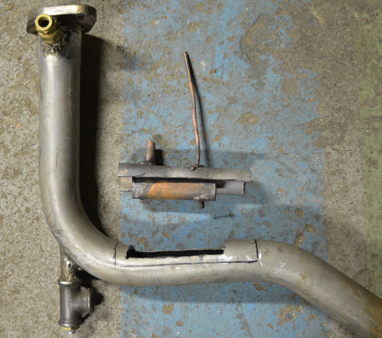
That's it action I have the stainless fittings I throw myself some little question my exhaust is 50mm diameter tube reactor 21mm.
Having passed my license Heavy truck recess the courses of méca still in mind ... the retarder al escaped .... should I that I enlarge the pot or not ??????? If not then c very simple level welding and gray matter if low I j expanded and go to a tube of 70mm to house the reactor you think what ????
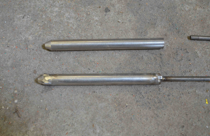
Ah yes another question is what is the interest of bevelling the end of the rod of the reactor? Where can I do it?
And ditto thread the reactor tube to connect the 1 / 2 T's because it costs an arm die for only 2 threading ...
Thank you for your answers
xav
That's it action I have the stainless fittings I throw myself some little question my exhaust is 50mm diameter tube reactor 21mm.
Having passed my license Heavy truck recess the courses of méca still in mind ... the retarder al escaped .... should I that I enlarge the pot or not ??????? If not then c very simple level welding and gray matter if low I j expanded and go to a tube of 70mm to house the reactor you think what ????
Ah yes another question is what is the interest of bevelling the end of the rod of the reactor? Where can I do it?
And ditto thread the reactor tube to connect the 1 / 2 T's because it costs an arm die for only 2 threading ...
Thank you for your answers
xav
0 x
timeisat wrote:That's it action I have the stainless fittings I throw myself some little question my exhaust is 50mm diameter tube reactor 21mm.
Having passed my license Heavy truck recess the courses of méca still in mind ... the retarder al escaped .... should I that I enlarge the pot or not ??????? If not then c very simple level welding and gray matter if low I j expanded and go to a tube of 70mm to house the reactor you think what ????
Ah yes another question is what is the interest of bevelling the end of the rod of the reactor? Where can I do it?
And ditto thread the reactor tube to connect the 1 / 2 T's because it costs an arm die for only 2 threading ...
Exhaust Retarder ?????
I'll say that shrinking the section of passage of the pot about 1 / 3 does not change much except near the full pot (but we will not, when we want to save!)
The shape of the rod outside the reduced play area does not change much to the music ....
For T, if you can avoid, avoid you will have less loss of load with softer forms.
0 x
Reason is the madness of the strongest. The reason for the less strong it is madness.
[Eugène Ionesco]
http://www.editions-harmattan.fr/index. ... te&no=4132
[Eugène Ionesco]
http://www.editions-harmattan.fr/index. ... te&no=4132
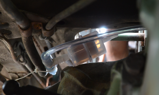
air intake??
good night everyone
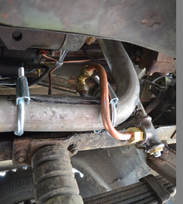
Well it is the reactor is soldering the gvi also I am fed water and air.
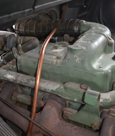
Question I planned to do my air stitching just behind my gas stitching at the air intake. Would it be better for me to poke the air inlet to the air filter or it's the same? Because on the intake duct the motor sucks in the air of the filter of my air intake will not be one but a vacuum cleaner
And since I made my mixture air / water from the gvi it may suck the water drip direct ds air intake ... I hope to be quite explicit ....
What do you think about what Flytox thinks because, fortunately, you're there to enlighten me, there are not many people on my post other than you.
please
@ + xav
Well it is the reactor is soldering the gvi also I am fed water and air.
Question I planned to do my air stitching just behind my gas stitching at the air intake. Would it be better for me to poke the air inlet to the air filter or it's the same? Because on the intake duct the motor sucks in the air of the filter of my air intake will not be one but a vacuum cleaner
And since I made my mixture air / water from the gvi it may suck the water drip direct ds air intake ... I hope to be quite explicit ....
What do you think about what Flytox thinks
please
@ + xav
0 x
Re: air intake ??
timeisat wrote:Question I planned to do my air stitching just behind my gas stitching at the air intake. Would it be better for me to poke the air inlet to the air filter or it's the same? Because on the intake duct the motor sucks in the air of the filter of my air intake will not be one but a vacuum cleaner
And since I made my mixture air / water from the gvi it may suck the water drip direct ds air intake ... I hope to be quite explicit ....
To be really understood, you would have to go through the diagram box ...
For air that will enter the GVI you can take it closer to the GVI, so without going back to the air filter (far = loss of load up), but with at least a small local air filter a fence end / sieve at a minimum that avoids unpleasant surprises. You can use a car fuel filter as an air filter with inlet / outlet in 6 mm diameter. For use with air this brakes relatively little.
0 x
Reason is the madness of the strongest. The reason for the less strong it is madness.
[Eugène Ionesco]
http://www.editions-harmattan.fr/index. ... te&no=4132
[Eugène Ionesco]
http://www.editions-harmattan.fr/index. ... te&no=4132


 and the reactor and its tube that did not want to be displayed all the time
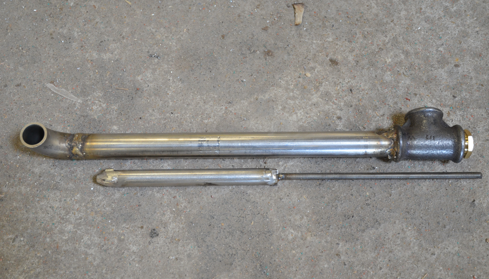
-
- Similar topics
- Replies
- views
- Last message
-
- 1 Replies
- 12139 views
-
Last message by Flytox
View the latest post
08/07/08, 19:58A subject posted in the forum : Water injection in engines: montages and experiments
-
- 30 Replies
- 38914 views
-
Last message by Mido66
View the latest post
12/05/09, 11:49A subject posted in the forum : Water injection in engines: montages and experiments
-
- 25 Replies
- 19418 views
-
Last message by bolt
View the latest post
28/02/06, 23:51A subject posted in the forum : Water injection in engines: montages and experiments
-
- 171 Replies
- 169936 views
-
Last message by phil 14
View the latest post
26/03/07, 23:23A subject posted in the forum : Water injection in engines: montages and experiments
Back to "Water injection in the engines: the assembly and experimentation"
Who is online ?
Users browsing this forum : No registered users and 95 guests