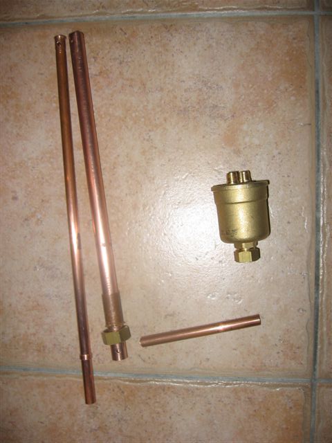
Andre wrote:The point that intrigues me is the body of the tubular rector copper
In my early try on comparisons with differrent materials, aluminum, steel, stainless steel, it is with the copper that I had the worst results, but it was a 100% panton mounting works on fuel oil on an engine a blast.
It may be quite different in doping water ..
Hi to you, Andre, model experimenter.
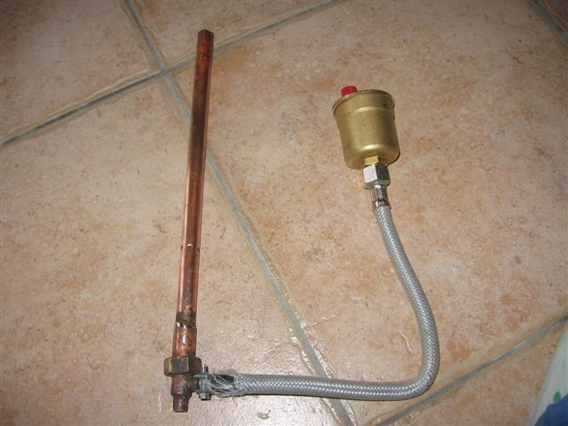
This assembly is "like that" because I could not do otherwise ...
- Copper is all I had on hand, otherwise I would have made of stainless steel.
- My vertical reactor ends below the exhaust, so not possible to install a steam generator below.
I had a good idea in mind since 3 months, but difficult to express.
The original idea was that "everything can fit", because on my tank the ingenious Citroën used all the space available under the hood to house the engine and its accessories.
- No room for a bubbler, I even had to put the water tank under the dashboard like a "passenger waterbag".
- No carbs on hand and a certain reluctance to use this machine of which I still cannot understand the subtleties ... I nevertheless followed the reference work "the pages of Mr. David" but there I blocked...
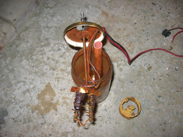
Then I thought of using the bottom of the reactor bubbler. But I know from experience that a mini bubbler causes liquid water and not steam. Hence the idea (quilted ...? On post No.?) Of the hollow rod.
And I remain convinced that my theory is not (completely) wrong:
- The swirling gases is essential for proper operation,
- The performance will be better if the tourbillon reached each cylinder (coupling
WITH a vortex)

- Steam must be and remain at a low temperature for a good ionization
My idea is that:
- If the installation is operational, the reactor end temperature drop should maintain just enough to allow boiling (50 °?)
- The intake air from the breather, circulating in the stem will prevent heat under the effect of: cavitation - the arc - other? (delete as appropriate)
In my humble opinion, the copper rod is malfunctioning because it leads so the heat it heats the incoming steam to the point of him exceed 100 ° C, or loss of ionization.
Here my bet is that the reactor outlet gas will remain at a low temperature, but strongly ionized and with a great angular velocity (see my theory which makes "seasoned" thermodynamicists cringe - citroën obliges

)