Need help connecting a programmer EG071

Hi-tech electronic and computer equipment and Internet. Better use of electricity, help with the work and specifications, equipment selection. Presentations fixtures and plans. Waves and electromagnetic pollution.
User avatar
fabio.gel
Éconologue good!
Éconologue good!
posts: 282
Registration: 06/03/08, 13:33
Location: 14 - Calvados
x 6

Need help connecting a programmer EG071


by fabio.gel » 30/12/12, 15:18

Hello

I got a weekly programmer 1 cycle path.
Hager EG071.

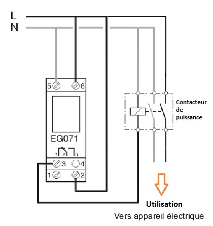
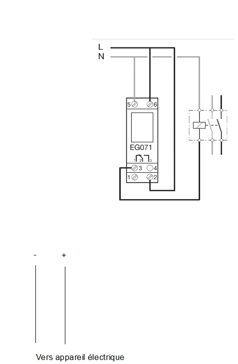
Following the diagram below that does not work then I have a doubt on the device.


Image

Two one thing is I Brele on connecting : Mrgreen:

or device sucks


Doc of the device:

http://www.google.fr/url?sa=t&rct=j&q=&esrc=s&source=web&cd=2&cad=rja&ved=0CD0QFjAB&url=http%3A%2F%2Fwaterheatertimer.org%2Fpdf%2FEG071_User_Instruction.pdf&ei=4UfgUNKIJZORhQeD5YHABQ&usg=AFQjCNExGkvfoJzDplFaGqA4dlHXqB2Avw&bvm=bv.1355534169,d.ZG4

If a charitable soul can tell me or what I branch the phase and neutral of the electrical appliance on this stuff bachibouzouc : Evil:

Thank you
0 x
I do my best to not leave trash world to my children ....
Alain G
Econologue expert
Econologue expert
posts: 3044
Registration: 03/10/08, 04:24
x 3


by Alain G » 30/12/12, 19:09

Hello Fabio!

In the diagram L = phase N = neutral, the unit can withstand a load too high so as indicated on the diagram you have to put an output switch and this switch you apply the load on the contact shown in gray and black.


Su you tried to directly connect it to the #2 contacts and #3 too much load the unit may be damaged.

Does the device indicate "On" on the screen?
0 x
Stepping behind sometimes can strengthen friendship.
Criticism is good if added to some compliments.
Alain
User avatar
fabio.gel
Éconologue good!
Éconologue good!
posts: 282
Registration: 06/03/08, 13:33
Location: 14 - Calvados
x 6

The relay works well


by fabio.gel » 30/12/12, 20:08

Alain G wrote:Hello Fabio!

In the diagram L = phase N = neutral, the unit can withstand a load too high so as indicated on the diagram you have to put an output switch and this switch you apply the load on the contact shown in gray and black.


Su you tried to directly connect it to the #2 contacts and #3 too much load the unit may be damaged.

Does the device indicate "On" on the screen?


When I press the ON / OFF button is well hear the relay is activated or deactivated.

Below a presentation of my wiring

Image
0 x
I do my best to not leave trash world to my children ....
Alain G
Econologue expert
Econologue expert
posts: 3044
Registration: 03/10/08, 04:24
x 3


by Alain G » 31/12/12, 08:16

: Shock:

Premièrememt in AC there is no positive and negative, and that makes you secondo with the red wire marked positive output?


Fashionable red wire with nothing on it must connect to the #3 terminal and the black on black at the entrance to the timer but if your load is too high it will not work this time because timer control but certainly not designed for power, and must have a switch on its output, you branch out as dependents?
:D
0 x
Stepping behind sometimes can strengthen friendship.

Criticism is good if added to some compliments.

Alain
User avatar
moulino51
I understand econologic
posts: 85
Registration: 27/02/12, 01:50
Location: On land near Reims
x 3


by moulino51 » 31/12/12, 09:04

And to illustrate Alain G

I'll have traced the wiring diagram you must achieve with a power switch (control of a radiator, for example)

Image

GS
0 x
User avatar
Forhorse
Econologue expert
Econologue expert
posts: 2486
Registration: 27/10/09, 08:19
Location: Perche Ornais
x 360


by Forhorse » 31/12/12, 09:34

+ 1 with alaing and moulino51
A small photo of your editing would be a plus to help us understand your mistake.

BTW, it's always connected with your ball history of resistance?
You do not have off-peak hours?
Because if yes, there's certainly a more streamlined mounting to do with your clock.
0 x
User avatar
fabio.gel
Éconologue good!
Éconologue good!
posts: 282
Registration: 06/03/08, 13:33
Location: 14 - Calvados
x 6

Shedder + programmer


by fabio.gel » 31/12/12, 10:08

Alain G wrote:: Shock:

Premièrememt in AC there is no positive and negative, and that makes you secondo with the red wire marked positive output?


Fashionable red wire with nothing on it must connect to the #3 terminal and the black on black at the entrance to the timer but if your load is too high it will not work this time because timer control but certainly not designed for power, and must have a switch on its output, you branch out as dependents?
:D


I have updated the schema following the explanation that you gave me.
By cons on the instructions it is written

- Output: 1 changeover contact
μ 16A - 250 v AC1
μ 3A - v cos fi = 250 0.6

what does this mean?.

If the final installation I like:

1) Activate the resistor has a period of night
2) Add load-shedding in the case of a forced march of day so that everything does not trip.

So a priori I'm going to have to invest in a power contactor will be between the clock and the resistance?

Thank you
0 x
I do my best to not leave trash world to my children ....
User avatar
fabio.gel
Éconologue good!
Éconologue good!
posts: 282
Registration: 06/03/08, 13:33
Location: 14 - Calvados
x 6

I understand the schema now


by fabio.gel » 31/12/12, 10:09

moulino51 wrote:And to illustrate Alain G

I'll have traced the wiring diagram you must achieve with a power switch (control of a radiator, for example)

Image

GS
0 x
I do my best to not leave trash world to my children ....
User avatar
fabio.gel
Éconologue good!
Éconologue good!
posts: 282
Registration: 06/03/08, 13:33
Location: 14 - Calvados
x 6

Another solution ?


by fabio.gel » 31/12/12, 10:10

Forhorse wrote:+ 1 with alaing and moulino51
A small photo of your editing would be a plus to help us understand your mistake.

BTW, it's always connected with your ball history of resistance?
You do not have off-peak hours?
Because if yes, there's certainly a more streamlined mounting to do with your clock.


If you have an idea, I'm interested : Idea:
0 x
I do my best to not leave trash world to my children ....
User avatar
moulino51
I understand econologic
posts: 85
Registration: 27/02/12, 01:50
Location: On land near Reims
x 3


by moulino51 » 31/12/12, 10:33

Between 1 and 3 you have an inverted contact, and already you should check with a multimeter if you have good contact between the 2 and 3 and if the contact is reversed between 2 and 1.

(important if it's Recycling equipment, to check the output of this switch)

You check has ohmmeter having disconnected the output son 2et3

GS
0 x


  • Similar topics
    Replies
    views
    Last message

Back to "Electricity, electronics and computers: Hi-tech, Internet, DIY, lighting, materials, and new"

Who is online ?

Users browsing this forum : No registered users and 282 guests