Hello
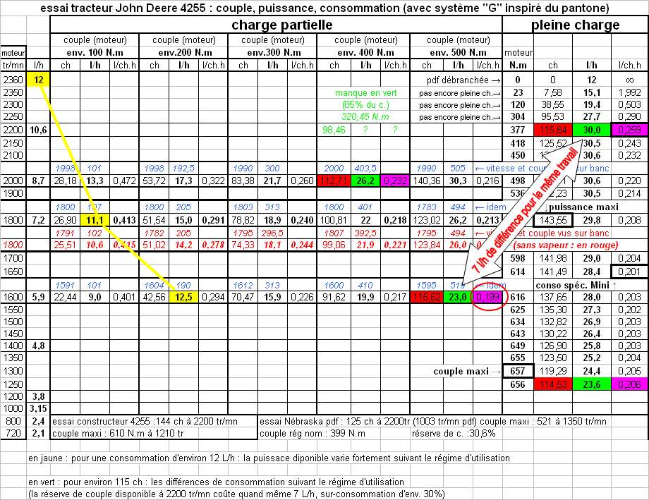
2) speed close to the maximum torque
Exactly like this that we adapt the cruise regime on aircraft engines. as a general rule when I change the pitch of the propeller, or when I install a larger one, I attach the solid plane to the ground and I rinse the engine at the bottom, the RPM indicated will serve me for the RPM of cruising, it is the maximum torque regime. because the plane stopped the propeller pumps all the air it is capable of, in flight it decreases the load, because the plane advances.
The economic regime corresponds to a motor loaded at its maximum torque.
Under speed and under low load, the engine forces too much to suck (butterfly slightly open) and it does not fill the cylinder well, its compression pressure is lower and it does not support lean mixing and normally we should increase the advance and its compression ratio to compensate ..
in under regime and very heavy load it begins to have too much mechanical friction and heat loss by walls in the cylinder head and cylinder, the engine heats up, at this level we should decrease the advance, the filling is done to the maximum the engine is more tolerant of the lean mixture, but more likely to
self-ignition if the fuel is a little limited for engine.
At full speed and (adjusted load) for this speed, you get the most out of the engine, but at the cost of high consumption, the filling of the cylinders no longer follows the speed of rotation, the torque decreases, the power curve begins to flatten and the power on these last laps is not so exploitable on an airplane with a propeller with fixed pitch. (not more on a car because of gearbox reports.)
I draw his observations on the different tests I do on the Lycoming and Continental engines of airplanes, although these are rustic and slow engines with high torque, the principle does not differ much on gasoline engines, just the revs and curves of power and torque which varies according to the design of the engine.
The only thing people relish is the maximum engine power, they forget to watch the torque.
It is necessary to have a power available on a broad range of mode, not to have all the power in high mode and almost nothing in the intermediate mode, the vehicle with this pointed engine is unpleasant to operate, it takes all a gearbox with many reports . It is this kind of engine that makes me sweat when it comes time to adapt a propeller for this plane.
Andre