Hello
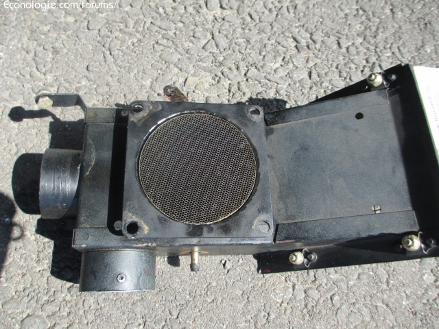
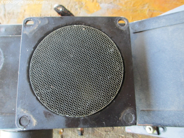
View of a forum Certain American puts a honeycomb grid just before the carburetor or the butterfly for injection engines
This improves the passage of air around the butterfly, when partially open, it improves the supply in the tubing more equal for multicylinders.
I pass the tests in 15 days on two lycoming engines one of 180hp and the other 135hp one is equipped with probe (EGT) exhaust (CHT) cylinder head, we will see if the temperatures are more uniform and also on the fuel flow meter
testing may take a few months.
There are two kinds of bee neither size tested
Honeycomb at engine inlet
-
- x 17
Hello,
Do they say how much the air flow is reduced, with this honeycomb?
I find this weird thing because, in general, we try to make the air filters as "passing" as possible to bring as much air as possible to the carburetor (s), and there we reduce the flow with a screen . I do not understand where is the gain? ...
Do you have details, or a link?
A+
0 x
-
- Moderator
- posts: 79364
- Registration: 10/02/03, 14:06
- Location: Greenhouse planet
- x 11060
André did not say that it replaced the classic air filter ...
I think there are 2 possible effects:
- improvement of turbulence before the fuel / injector = improvement of the homogeneity of the mixture
- air friction at the grid = combustion air ionization = combustion improvement (we come back to the explanation of water doping)
I think there are 2 possible effects:
- improvement of turbulence before the fuel / injector = improvement of the homogeneity of the mixture
- air friction at the grid = combustion air ionization = combustion improvement (we come back to the explanation of water doping)
0 x
Do a image search or an text search - Netiquette of forum
Hello
This is the grid I just bought to put on the Lycoming
it will be placed just before the entry of the carburetor, its goal is to calm the turbulences with the passage of the venturia and then to the butterfly valve and to give an equal distribution to the four cylinders autravers the long pipes, which are source of differrential of exhaust temperature, and vibration.
The first photo of the post the grid is thinner (thousands of GM V6 V8 multi-point injection engines have these honeycomb grids, it is placed just before the mass air flow.
It is not an air filter, the restriction is minimal on a medium displacement engine.
For the moment I can not comment on the advantages or disadvantages of this grid in front of a carburetor
it is only after tests and measurements that one will be able to know.
Andre
0 x
-
- Moderator
- posts: 79364
- Registration: 10/02/03, 14:06
- Location: Greenhouse planet
- x 11060
Improve laminar? Ah well it's the opposite of what I thought ...
0 x
Do a image search or an text search - Netiquette of forum
Christophe wrote:Improve laminar? Ah well it's the opposite of what I thought ...
It may be the opposite, the flow was no longer laminar because of the contortions / surface condition / various probes of the intake duct and we force it to become again before an organ where we need homogeneity (flowmeter, nozzle etc ...). It is a trick used in wind tunnels (aerodynamic test, cars / planes etc ...) following notably pronounced turns (90 °).
0 x
Reason is the madness of the strongest. The reason for the less strong it is madness.
[Eugène Ionesco]
http://www.editions-harmattan.fr/index. ... te&no=4132
[Eugène Ionesco]
http://www.editions-harmattan.fr/index. ... te&no=4132
There the size is impressive in this wind tunnel (Renault): mrgreen:, but the principle remains the same all these appendages are used to restore a flow as laminar as possible after a disturbance.
0 x
Reason is the madness of the strongest. The reason for the less strong it is madness.
[Eugène Ionesco]
http://www.editions-harmattan.fr/index. ... te&no=4132
[Eugène Ionesco]
http://www.editions-harmattan.fr/index. ... te&no=4132
Back to "Special motors, patents, fuel consumption reduction"
Who is online ?
Users browsing this forum : No registered users and 376 guests