Chinese Electric Hybrid Scooter Bike Repair

Cars, buses, bicycles, electric airplanes: all electric transportation that exist. Conversion, engines and electric drives for transport ...
Christophe
Moderator
Moderator
posts: 79364
Registration: 10/02/03, 14:06
Location: Greenhouse planet
x 11060

Chinese Electric Hybrid Scooter Bike Repair


by Christophe » 10/02/09, 18:33

This is a follow-up to LeJuste's generous donation of a Chinese hybrid scooter bike that he has found and that I am trying to refurbish.

https://www.econologie.com/forums/j-ai-trouv ... t7008.html

Here are the "standard" equipment

- flashing (on the front it is certain, on the back can be I have not yet been able to identify)
- lighthouse av / ar
- stop light
- accelerator
- brake (1 mini drum on the back only)
- comodo cuts everything
- Horn
- LED battery charge (if yes!)

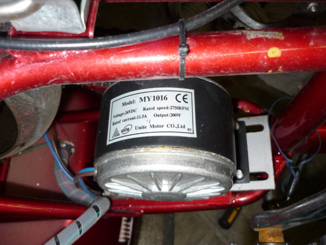
Everything is in 24V DC, same for the engine, it is a 200W engine.

All this makes me think (especially the throttle and the gauge) that it is not an electric bike but a hybrid scooter-bike ...

By turning the wheel by hand (without going through the chain: there is a free wheel so impossible) the engine leaves the 4 5 V: it seems perfectly reversible!

Here are some pictures of the autopsy!

The 24VDC 200W engine:

Image

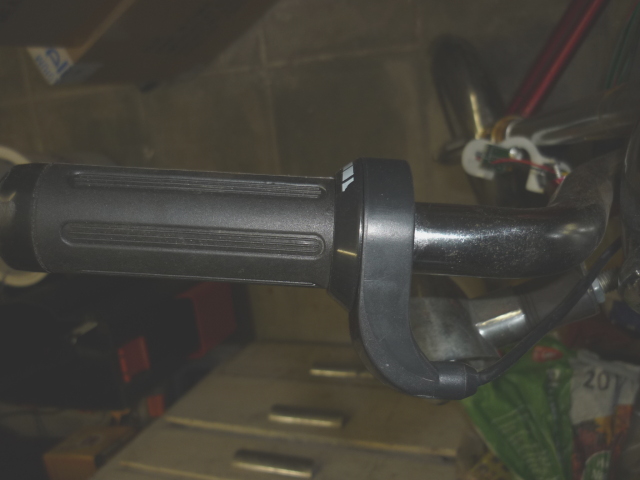
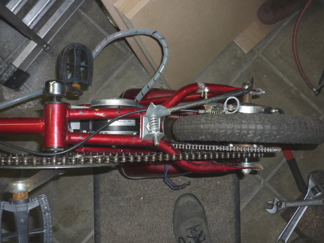
Right handlebar: accelerator.

Image

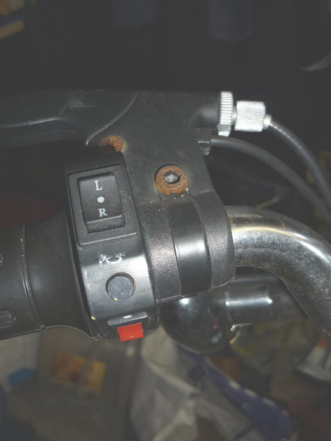
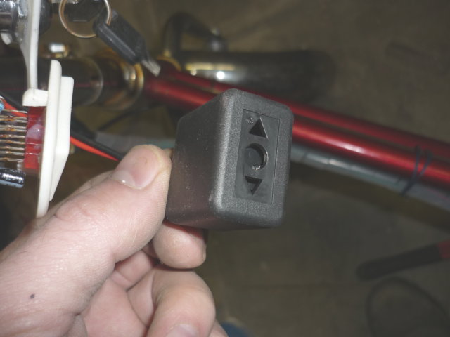
Left handlebar: flashing, horn, fire (but I think not used according to the wiring) and a brake light on the single brake (rear).

Image

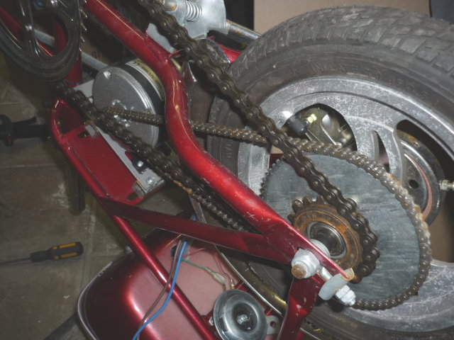
General view of the transmission with mini drum brake and kickstand:

Image

Image

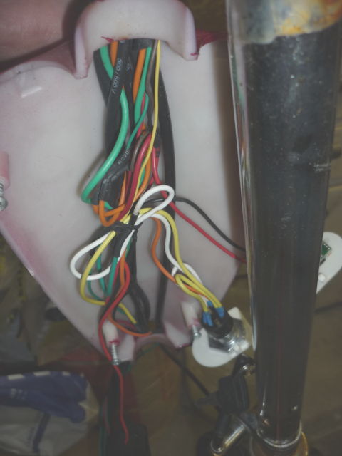
Part of the beam: fortunately there is color but 1 cable can change color several times between the front and the back !!

Image

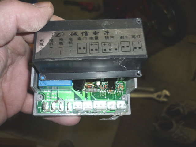
The commodo and the load "gauge":

Image

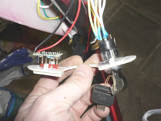
The flashing control:

Image

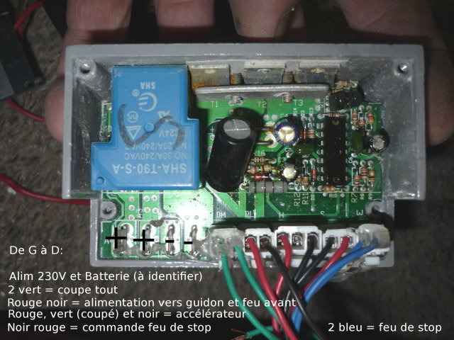
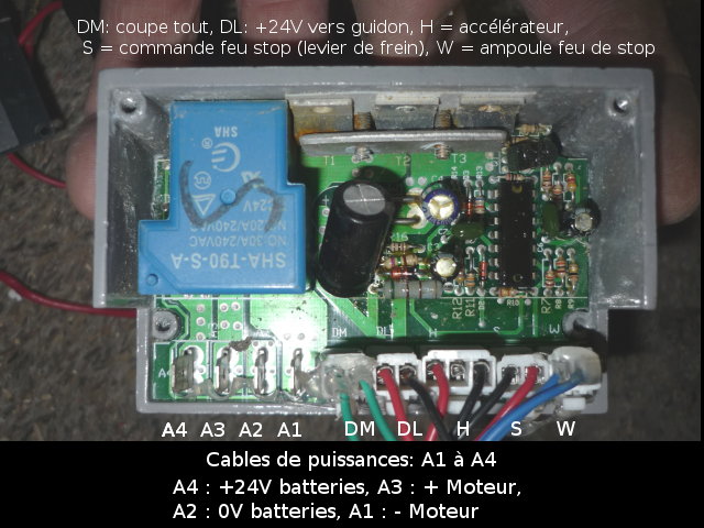
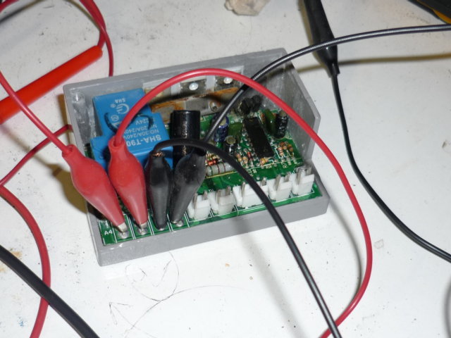
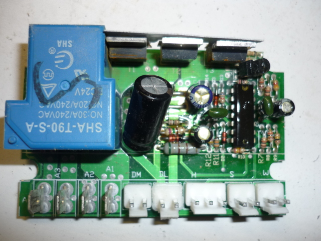
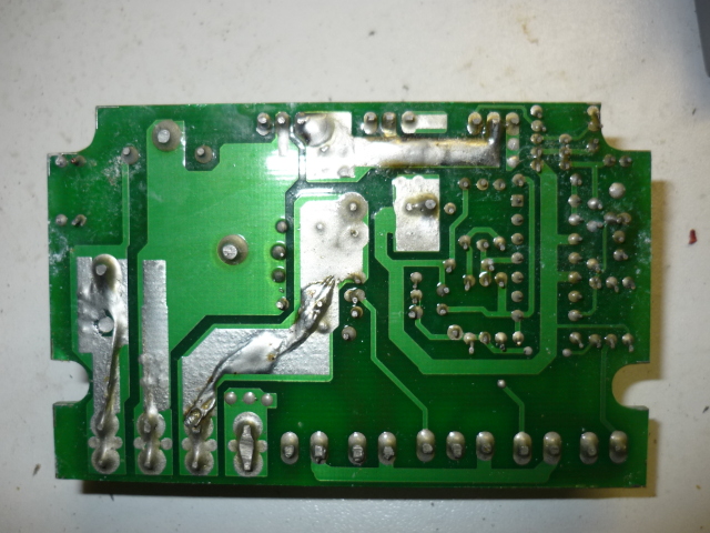
The power station (which LeJuste had already photographed), it is apparently powered directly 230V (and must therefore contain the battery charging circuit).

Image

Image

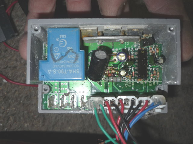
I am trying to identify the different pods, I have "undone" the whole bundle for this.

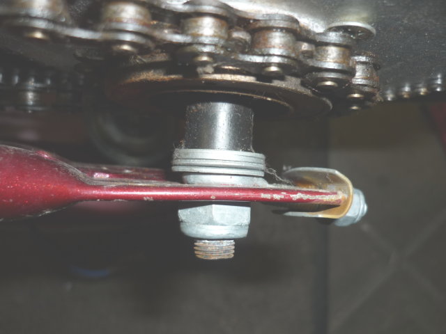
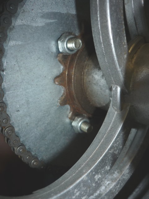
Here are 2 details that "kill" that show the level of design and that we would never find on a non-Chinese road device :)
- the swarmers on the rear wheel axle
- the coupling of the engine crown on the wheel with 4 screw bolted on an old pinion!

Image
Image

I start to wonder if this vehicle is homologated for us (which would explain its abandonment!) ...

I identify the different cables right now!
Last edited by Christophe the 10 / 02 / 09, 19: 29, 1 edited once.
0 x
Christophe
Moderator
Moderator
posts: 79364
Registration: 10/02/03, 14:06
Location: Greenhouse planet
x 11060


by Christophe » 10/02/09, 19:18

Here is for the identification of the cables at the level of the "central":

Image

It remains to identify 2 power supply: as much 230 as 12V but it should not be too difficult.

One thing is on: everything is in 24V DC, because even the flashing bulbs are in 24V!

Edit: solution

Image
Last edited by Christophe the 16 / 02 / 09, 15: 44, 1 edited once.
0 x
Christophe
Moderator
Moderator
posts: 79364
Registration: 10/02/03, 14:06
Location: Greenhouse planet
x 11060


by Christophe » 10/02/09, 19:24

Ah it may not be 230 V which happens because the blue sha t90 SA thing is certainly a relay in 230 but ... I have a doubt because the "legend" is strictly identical between the low voltage and the 230V ...

Image
0 x
Christophe
Moderator
Moderator
posts: 79364
Registration: 10/02/03, 14:06
Location: Greenhouse planet
x 11060


by Christophe » 10/02/09, 21:38

And if the ++ - was the wiring for 2 12V battery and that there was no 230V that would arrive in the scooter (external transformer 12V necessary for charging).

12 + 12 = 24V (if yes!)

That would explain the completely identical legends on the case!
0 x
Christophe
Moderator
Moderator
posts: 79364
Registration: 10/02/03, 14:06
Location: Greenhouse planet
x 11060


by Christophe » 10/02/09, 21:44

Oh no it's not possible because it would miss the power of the engine ...

Rolalala not easy :)

Will test the board in my "lab" ...
0 x
User avatar
gegyx
Econologue expert
Econologue expert
posts: 6991
Registration: 21/01/05, 11:59
x 2914


by gegyx » 10/02/09, 22:05

SHA T90 -SA RELAY
I only found that by looking foolishly.
See with the number of pins ...

http://www.shrelays.com/en/productShow.asp?id=682

http://www.alibaba.com/product-gs/20699 ... 0_12v.html
0 x
Christophe
Moderator
Moderator
posts: 79364
Registration: 10/02/03, 14:06
Location: Greenhouse planet
x 11060


by Christophe » 10/02/09, 22:20

This is exactly the 1er link but in 24V (12V in the photo), congratulations for the search (I found the 2ieme link)

Yes it is a relay 24V DC am miro I had not seen the indication on under the black marker! : Mrgreen:

So there is no 230 coming on this turntable ... so there was necessarily another transformer somewhere to switch to 12 or 24V.

I start the TP!
0 x
Christophe
Moderator
Moderator
posts: 79364
Registration: 10/02/03, 14:06
Location: Greenhouse planet
x 11060


by Christophe » 10/02/09, 23:15

1er results of the TP, I simulated 2 batteries thanks to 2 stabilized power supply 12V DC:

Image

B1 = 1 Voltage Battery V1
B2 = 2 Voltage Battery V2

The wiring from L to D is apparently in this order:

B1 + V1, B2 + V2, B2 0V, B1 0V

I simulated the stopping of a battery and the other to see who does what: B2 supplies the brake light, the accelerator (10,7 V between pins 1 and 2 and 1 and 3, 0 between 2 and 3) and power supply to the handlebars.

B1 only feeds 2 green wires which finally are certainly not the circuit breaker (even if they go to comodo).

The voltage on these 2 son V1 + V2 with a slight loss (2 to 3%).

I do not know how powered the engine is. I'm wrong can be at the wiring and a battery would be the output for the engine?

Here is the bottom of the plate for specialists (the back is "inverted" so that it corresponds to the front photo) it is welded like a pig (I weld better that is to say!):

Image
Image
0 x
dirk pitt
Econologue expert
Econologue expert
posts: 2081
Registration: 10/01/08, 14:16
Location: isere
x 68


by dirk pitt » 11/02/09, 09:23

from what I see of the circuit, the 4 big pods of powers would be affected like this:

A4 = + 24V battery
A3 = + motor
A2 = - Battery
A1 = - Engine

The relay serves as a general power cut-out. (probably activated at the key contact: 2 green wires connected)

no 220v on this card. in general on these machines, the charger is external and there is in the battery circuit (upstream of this card) a charge directly in // on the batteries.
0 x
Image
Click my signature
Christophe
Moderator
Moderator
posts: 79364
Registration: 10/02/03, 14:06
Location: Greenhouse planet
x 11060


by Christophe » 11/02/09, 10:28

Ok I will test this config. But according to the tests it would be rather the opposite:

A4 = + Engine
A3 = + 24V
A2 = - Engine
A1 = 0V

Indeed; by putting 12V between A4 and A2, the platinum does not react well.

I shunted in all the configs tested yesterday 2 son green to see if it changed something: nothing.

I will dismount the accelerator and plug it on the board to simulate correctly.
0 x


  • Similar topics
    Replies
    views
    Last message

Back to "Electric transport: cars, bicycles, public transport, planes ..."

Who is online ?

Users browsing this forum : No registered users and 232 guests