
18 January 2006. Climens Aimé: last update of the MEG machine.
Key words: MEG, Bearden, surunity, electricity, magnetism, magnet.
Introduction
The Bearden MEG is an assembly that would "pump" the energy of permanent magnets. There are many experiences, but to our knowledge none has succeeded in producing sustainable usable energy.
Here is the testimony of an experimenter. Click on images to enlarge.
Author's explanations.
Initially we seek to extract free energy from a permanent magnet.
The first practical requirement is that the demagnetizing field be much lower than the
coercive field. This condition is historically possible recently with magnets
To "rare earths" such as those using the iron boron neodymium alloy.
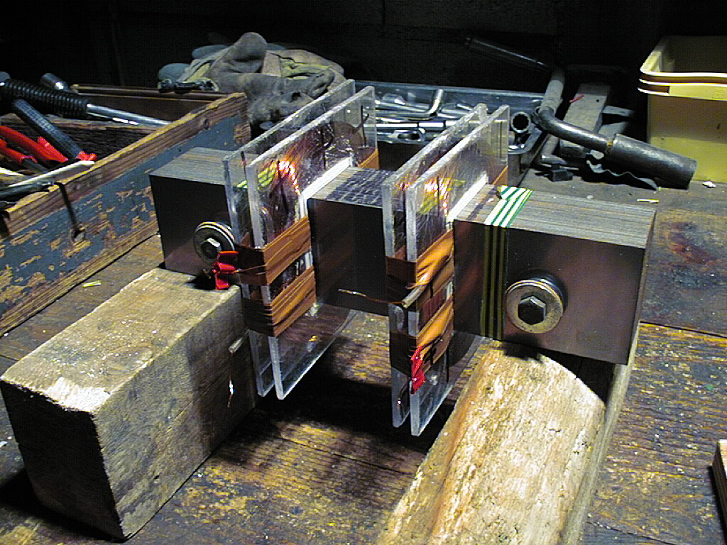
The clever idea of Bearden is to use a double magnetic circuit whose length is common and whose section is uniform in any place of this double magnetic circuit.

The permanent magnet is located on the length common to both circuits.
To produce electrical energy with this system, it is necessary to install power collecting coils in each of the two magnetic circuits. These coils will each be connected to a "load" expressing the production of energy (bulbs for example).
A coil inserted into a magnetic circuit can produce electrical energy only when the flow through the circuit varies in intensity in a given time.
At rest of the system, the permanent magnet distributes its flux equally in the two magnetic circuits because their reluctance is equal due to their appropriate construction.
If a mechanism forces the flux of the permanent magnet to flow in a single branch
Double magnetic circuit it will change the flow in this circuit and therefore
Creation of energy in the coil concerned by this increase of flux.
On the other hand the coil of the circuit where the flow disappears will also be the seat of a production of energy because the flow is also modified but upside down. So the meaning of
Running current in this coil will be the opposite of the other.
What mechanism can change the flux distribution of the permanent magnet?
The variation of reluctance in one of the branches of the double circuit. To obtain this variation of reluctance, a saturated flat coil will be used. Indeed the material of the magnetic circuit has a magnetic permeability which varies with the magnetic induction that runs through it. If we obtain on a short length of this circuit a "saturating" induction with a flat coil, we create a kind of gap where the permeability is that of air. So we will create a strong reluctance in the circuit concerned. The flux of the magnet
Permanent will therefore be distributed pro rata reluctance and therefore favor the unsaturated circuit.
The flat coil being inserted in a ferrous magnetic circuit will have an inductance which will be a function of the square of the number of its turns and the section and the length of its magnetic circuit. This inductance will oppose the instantaneous variation of the fluxes.
Thus the duration of establishment of the saturating field of the control coil will build the electrical parameters that will appear in the energy receiving coils. The fewer turns in the control coil, the higher the voltage induced in the energy collecting coils. But also the production time will be short.
The efficiency of the MEG depends on several parameters.
First, it is necessary to precisely calculate the saturation point of the control coils to save the ohmic losses of the coils. Then it is interesting to use a magnetic circuit material with high permeability and low loss by eddy currents. The high permeability will be used to obtain saturating ampere-turns with less energy expended.
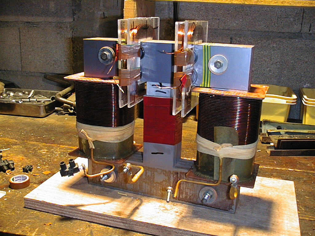
The flat control coils must not exceed a certain diameter, as this may reduce their efficiency, which leads to the use of high current density coils which must therefore be cooled in the oil so as not to raise their temperature, which would increase ohmic losses and could degrade their insulators.
At this point it should be noted that the MEG expresses its power when there is permutation of the control coils. Indeed, when the first control coil is connected to a direct current, the displaced flux of the permanent magnet is equal to half of the total flux.
But when it is switched with the other coil, it is the totality of the flux that moves and we thus obtain the maximum energy on the energy collecting coils without
the expense of the control coils increases.
For practical reasons of energy recovery, a diode of the same direction will be inserted on each collecting coil, which will make it possible to obtain a current with the same "pulsed continuous" direction suitable for charging capacitors or a battery, for example. If we did not do so we would have in each coil a succession of contrary currents due to the growth then to the decay of the flows. We will obtain all the energy alternately in one coil then in the other.
For the moment the best permutation is obtained by mechanical pressure of the contacts
Because the passage of the amperes is related to the inverse of the distance between the contacts to suppress the ohmic losses.
A last very important problem is the management of counter currents induced in the energy receiver coils. In fact, when the receiver coils are connected to a load, a current is established which opposes the variable flow that produced it. This "counter current" issued
the production of energy therefore produces itself a flux coming from the receiver coil and which will have to find a way in the double magnetic circuit. 2 paths are available for the passage of this flow: the path where the permanent magnet is located and the path where the control coil is located. Both paths have high reluctances. The path of the magnet is the worst because the permanent magnet crossed by a foreign flux has a
permeability barely above the air is mu = 1,05.
In our construction the length of this magnet in its circuit is 25 mm is a huge reluctance. The path of the control coil is of less reluctance because its length in the circuit is 10 mm.
So it will pass a counter flow in the control coil about 3 times greater than that which will pass in the magnet: or a "transformer" effect by lowering the induction movement of the control coil causing a current draw outside to return to saturation.
In fact, in the control coil, the introduction of the direct current causes the saturation flux to be created and at the same time the opposite current which opposes it, thus limiting the input energy consumption. The control coil of our system consumes 4 amperes in steady state and 1 amp transient but 2 amps under a
Charge of 20 watts. The countercurrent of production thus opposes the countercurrent of consumption.
We can turn the problem around. The production of energy in the receiver coil therefore leads to the creation of a current which itself creates a counter flow to the one who created it. This flow created by
The reel must come out and come back by any way. We can therefore create a specific path with low reluctance.
For example, a second external circuit may be attached to the magnetic circuit of the receiver coil, the section of which will be smaller so as not to take up too much flux from the permanent magnet, but will be sufficient to have a path of much less reluctance than that passing through the magnet. magnet on the control coil. The proportions remain to be established by the experiment to obtain the maximum of energy. It should be noted that this system would eliminate the "transformer effect" in the control coil because a tiny part of the counterflow would cross through it because of the preference of magnetic flux for the least reluctance.
This new parameter is surely the condition of the unit because the intensity produced in the receiver coils will not be slowed by the weakness of the opposite flow that it generates.
A hope of surunity?
Thursday 2 February 2006. Climens Aimé: about MEG performance
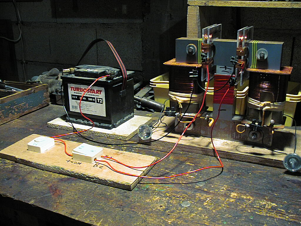
Yesterday he took the curiosity to measure the voltage across one of the control coils connected to a battery of 12 volts with a "metrix" Needle.
In the absence of permutation of the control coils the intensity traversing these coils is 4 ampere is 48 watts consumed. If you switch the coils with a load of 20 watts (a bulb 12 volts iodine 20 watts so) we get an intensity of 2 amps consumed by the control coil. Is…
This would make a consumption of 24 watts for a production of 20 watts
At the output of the power coils. The yield would be 83%.
The surprise is that the voltage at the input of the connected control coil and in
The permutation scheme with a load of 20 watts is 6 volts, which is a power consumption of 12 watts for a production of 20 watts. Now it is clear that the power consumed is measured at the terminals of the active system. I measured the voltage so far across the battery and could not find anything other than 12 volts for a battery in good condition and charged. The "counter-voltage" opposite to that of the battery can come only from the operation of the MEG, not from the switching which is a passive system even consuming (by ohmic loss on the contacts).
So the yield is 166%, a material manifestation of on unit.
It would therefore remain 8 free watts.
The problem of the weakness of the unit power per volume of the device is still not solved and I continue the test of bypass circuit against the flow in the power coils.
To be continued